c. Save all the packing materials in case you need to return the SFP
transceiver.
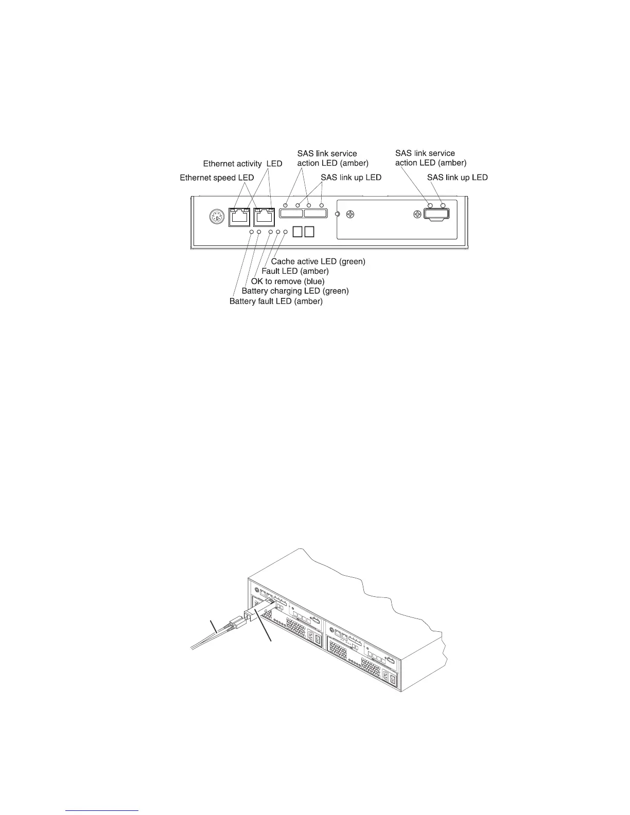
5. To locate a failed SFP transceiver in the DS3500 controller-drive enclosure,
look at the Host Link LEDs on the rear of the controllers. Both Host Link
LEDs for a particular port are off if an SFP transceiver fails.
v If both Host LEDs are off for a particular port – You must replace the SFP
transceiver. Go to step 6.
v If at least one Host LED is on for a particular port – The SFP transceiver is
functional. The Host LEDs indicate a channel speed of 2 Gbps, 4 Gbps, or 8
Gbps.
Attention: Potential degraded performance – To prevent degraded
performance, do not twist, fold, pinch, or step on fiber-optic cables. Do not
bend the fiber-optic cables tighter thana5CM(2INCH.) radius.
Note: The Controller Service Action Required LED comes on whenever a loss
of a path occurs. The storage management software’s enclosure Component
information dialog provides both channel information and port information to
help you identify the components that are in the path.
6. If it is present, disconnect the fiber-optic cable from the failed SFP transceiver.
7. Remove the failed SFP transceiver from the interface port. Refer to the
procedure for “Removing SFP modules” on page 38
Figure 120. Controller LEDs
SFP
module
Fiber optic
cable
dg1fy115
Figure 121. Installing an SFP module into the host port
Chapter 5. Replacing components 155
 Loading...