later, see IBM System Storage DS Storage Manager Version 10.8 Installation and Host
Support Guide. Save the profile in a location other than in the logical drives that
are created for the DS3500 storage subsystem and EXP3500 storage enclosure.
v During any maintenance or attended power-on procedure, carefully follow the
power-on sequence that is described in “Turning on the storage subsystem” on
page 82. Ensure that each component of the storage subsystem is powered-on in
the correct order during this entire power-on procedure to ensure that the
controller will be able to optimally access all of the storage subsystems.
v The storage subsystem supports simultaneous power-on to the system
components. However, you must always follow the power-on sequence that is
described in “Turning on the storage subsystem” on page 82 during any
attended power-on procedure.
v A storage subsystem in an optimal state should recover automatically from an
unexpected shutdown and unattended simultaneous restoration of power to
system components. After power is restored, call your IBM technical-support
representative if any of the following conditions occur:
– The storage subsystem logical drives and subsystems do not display in the
Storage Manager graphical user interface.
– The storage subsystem logical drives and subsystems are not online.
– The storage subsystem logical drives and subsystems seem to be degraded.
v When using dc models equipped with dc power supply and fan units, install the
dc disconnect/breaker device as described in “Cabling the DS3500 and EXP3500
dc power supplies” on page 78.
Attention:
– The disconnect device (circuit breaker) must be rated at 20 A.
– Ensure that only 12 AWG or larger copper conductor wires are used for all of
the wiring between the DS3500 or EXP3500 dc power connectors and the dc
power source.
DS3500 storage subsystem and EXP3500 storage enclosure
components
The DS3500 storage subsystem and EXP3500 storage enclosures have removable
components, as described in this topic.
The DS3500 storage subsystem and EXP3500 storage enclosures have the following
removable components. These components, called customer replaceable units
(CRUs), are accessible from the front or rear of the storage subsystem.
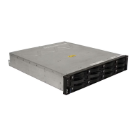
v (DS3512 and EXP3512) Up to 12 LFF 3.5–inch 6 Gbps SAS or NL SAS drives and
drive filler panels.
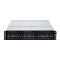
v (DS3524 and EXP3524) Up to 24 SFF 2.5–inch 6 Gbps SAS, NL SAS, or SSD
drives and drive filler panels.
v (DS3512 and DS3524) Up to two controllers. Each controller supports the
installation one of the following optional host port adapters:
– 6 Gbps SAS
– 8 Gbps FC
– 1 Gbps iSCSI
– 10 Gbps iSCSI
v (EXP3512 and EXP3524) Up to two ESM modules.
v Two ac power supply and fan units (machine type 1746 models C2A, E2A, C4A,
and E4A).
Chapter 1. Introduction 9
 Loading...