Chapter 2. Architecture and technical overview 29
Draft Document for Review May 28, 2009 1:59 pm 4405ch02 Architecture and technical overview.fm
Table 2-2 EnergyScale function’s software interfaces
2.3 Processor cards
In the 570, the POWER6 processors, associated L3 cache chip, and memory DIMMs are
packaged in processor cards. The 570 uses a dual-core processor module for a 2-core,
4-core, 8-core, 12-core, and 16-core configuration running at 3.5 GHz, 4.2 GHz, or 4.7 GHz.
The 570 has two processor sockets on the system planar. Each socket will accept a
processor card feature. A single CEC may have one or two processor cards installed. A
system with two, three, or four CEC must have two processor cards in each CEC.
Each processor can address all the memory on the processor card. Access to memory
behind another processor is accomplished through the fabric buses.
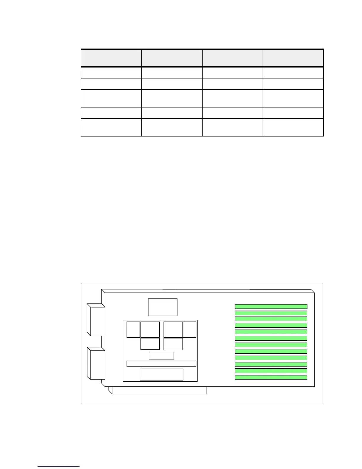
The 2-core 570 processor card contains a dual-core processor chip, a 36 MB L3 cache chip
and the local memory storage subsystem.
Figure 2-3 shows a layout view of a 570 processor card and associated memory.
Figure 2-3 The 570 processor card with DDR2 memory socket layout view
The storage structure for the POWER6 processor is a distributed memory architecture that
provides high-memory bandwidth, although each processor can address all memory and
EnergyScale
functions
ASMI HMC Active Energy
Manager
Power Trending N N Y
Power Saver Mode Y Y Y
Schedule Power Saver
Mode Operation
NYY
Power Capping N N Y
Schedule Power
Capping Operation
NNY
Memory
controller
POWER6
core
POWER6
core
Altivec Altivec
L2 Cache
4 MB
L2 Cache
4 MB
L3 ctrl
Fabric bus
Memory
controller
L3
Cache
Memory dimms
 Loading...