Do you have a question about the IBM Power 570 and is the answer not in the manual?
Lists general system specifications including operating temperature, humidity, noise, and altitude.
Details the physical attributes and dimensions of the CEC drawer building blocks.
Outlines key features like core configurations, memory capacity, and disk drive support.
Describes processor card types, frequencies, cache, and Capacity on Demand (CoD) options.
Details memory feature codes, capacities, frequencies, and population rules.
Explains the types of I/O drawers, their slots, and connectivity options.
Covers rack compatibility, features, and installation considerations for the system.
Describes the features and specifications of the 1.8-meter IBM 7014 Model T00 rack.
Details the characteristics and function of the Intelligent Power Distribution Unit.
Explains the POWER6 processor's enhancements, core architecture, and advanced features.
Details the decimal floating-point processor's support for data types and instructions.
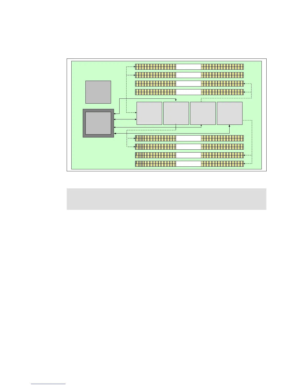
Describes the POWER6 processor cards, their layout, and memory interfaces.
Covers the memory controller, DIMM slots, and memory architecture.
Explains the fully buffered DIMM technology for enhanced memory performance.
Details the IVE adapter, its features, ports, and system integration.
Discusses PCI and PCIe adapter types, slots, and general support.
Lists available LAN adapters for connecting to a local area network.
Explains the iSCSI protocol for storage transport over IP networks.
Covers the internal disk subsystem using SAS interface and DASD backplane.
Describes external I/O drawers like 7311-D11, 7311-D20, and 7314-G30.
Details the 7311 Model D11 I/O drawer's features and slot configurations.
Explains the HMC's role in managing system tasks and partitions.
Introduces the POWER Hypervisor as a core component for system virtualization.
Describes the virtual SCSI mechanism for storage virtualization using VIO Server.
Explains the virtual Ethernet switch function for secure inter-partition communication.
Discusses LPARs and virtualization for resource utilization and configuration.
Details Micro-Partitioning for allocating processor fractions to logical partitions.
Covers the PowerVM platform for industry-leading virtualization.
Outlines the functional elements of PowerVM Standard and Enterprise editions.
Explains the VIO Server's role in sharing physical resources among logical partitions.
Describes moving running logical partitions between systems without disruption.
Explains the SPT for designing system configurations and planning partitions.
Discusses the design principles for achieving high system reliability.
Covers design choices that reduce failure opportunities and improve reliability.
Details features that prevent unexpected application loss due to outages.
Explains monitoring and deconfiguring faulty hardware to avoid system outages.
Outlines the strategy for efficient system service and repair.
Covers the critical ability to accurately detect system errors.
Explains how systems perform self-diagnosis using hardware and OS logic.
Details methods for quickly identifying and replacing service parts.
Covers functions and tools for efficient system management.
Describes the service processor's role in monitoring, managing, and error detection.
Explains the process of managing and installing microcode updates.
Lists IBM Redbooks relevant for detailed discussion of topics.
Provides links to relevant IBM websites for further information.