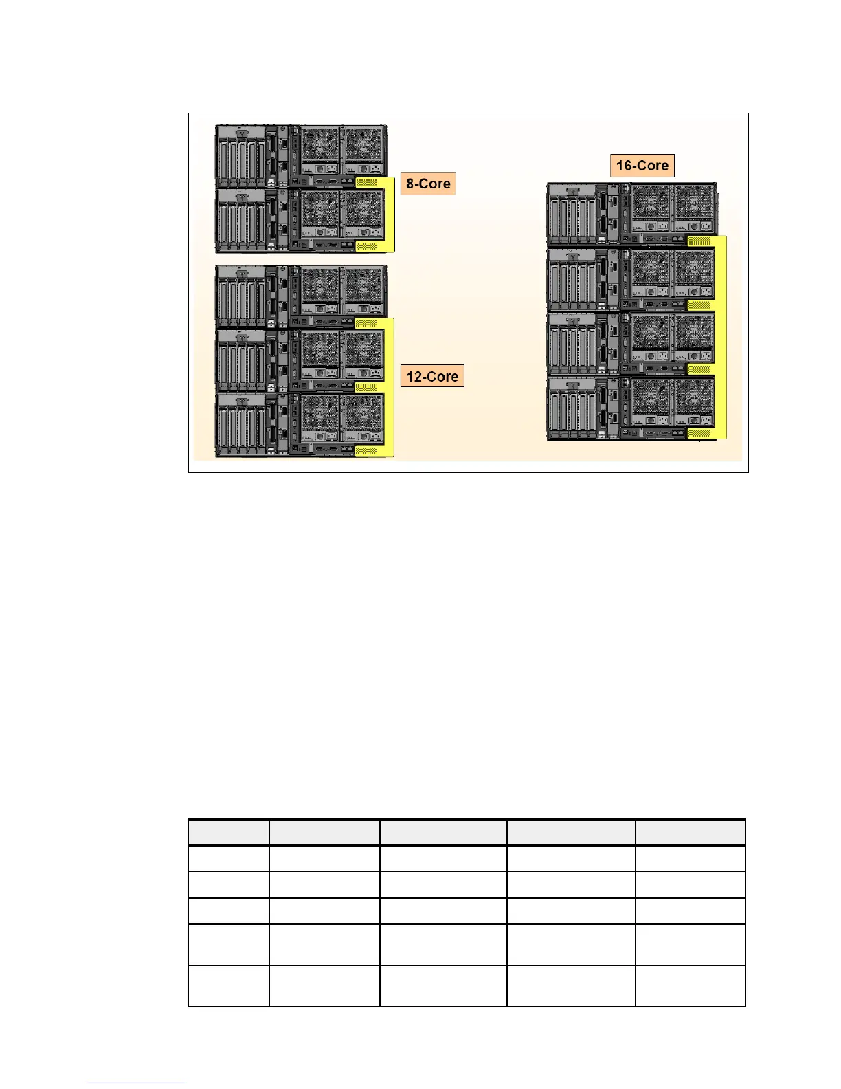
Chapter 2. Architecture and technical overview 37
Draft Document for Review May 28, 2009 1:59 pm 4405ch02 Architecture and technical overview.fm
Figure 2-9 SP Flex™ cables
FC 5657: 2-drawer SP cable
FC 5658: 3-drawer SP cable
FC 5660: 4-drawer SP cable.
2.6 Internal I/O subsystem
The internal I/O subsystem resides on the system planar which supports a mixture of both
PCIe and PCI-X slots. All PCIe or PCI-X slots are hot pluggable and Enhanced Error
Handling (EEH) enabled. In the unlikely event of a problem, EEH-enabled adapters respond
to a special data packet generated from the affected PCIe or PCI-X slot hardware by calling
system firmware, which will examine the affected bus, allow the device driver to reset it, and
continue without a system reboot.
Table 2-5 display slot configuration of 570.
Table 2-5 Slot configuration of a 570
Slot# Description Location code PHB Max Card Size
Slot 1 PCIe x8 P1-C1 PCIe PHB0 Long
Slot 2 PCIe x8 P1-C2 PCIe PHB1 Long
Slot 3 PCIe x8 P1-C3 PCIe PHB2 Long
Slot 4 PCI-X DDR,
64-bit, 266 MHz
P1-C4 PCI-X PHB1 Long
Slot 5 PCI-X DDR,
64-bit, 266 MHz
P1-C5 PCI-X PHB3 Long