Options applicable to expansion enclosures
__ v Expansion enclosure attachment cables
__ v Drives
__ v DC power supply (if applicable to the feature number ordered)
__ v Power cords for connection to wall sockets
Identify the hardware components
The following graphics identify the hardware components and port locations for
the control enclosure and expansion enclosure on the system.
Control enclosure components
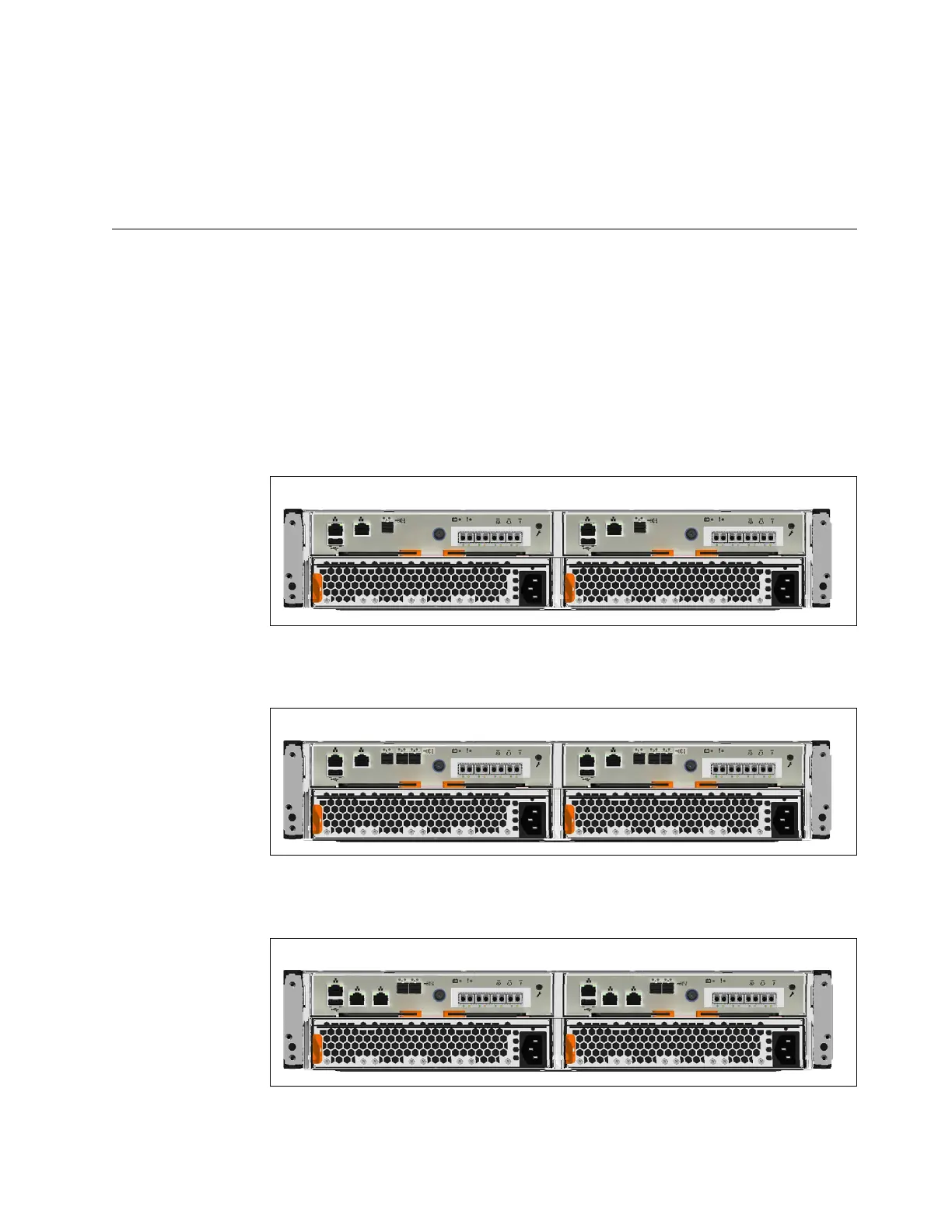
The following figures show the rear view of the control enclosures on Storwize
V5000 Gen2 systems. The location of the power supply units and node canisters
are also shown.
Figure 1 shows the Storwize V5010 control enclosure.
Figure 2 shows a rear view of the Storwize V5020 node.
Figure 3 shows a rear view of the Storwize V5030 and Storwize V5030F node.
Data ports
Figure 1. Storwize V5010 control enclosure
Figure 2. Storwize V5020 control enclosure
Figure 3. Storwize V5030 and Storwize V5030F control enclosure
Chapter 1. Before you begin the installation 7
 Loading...


