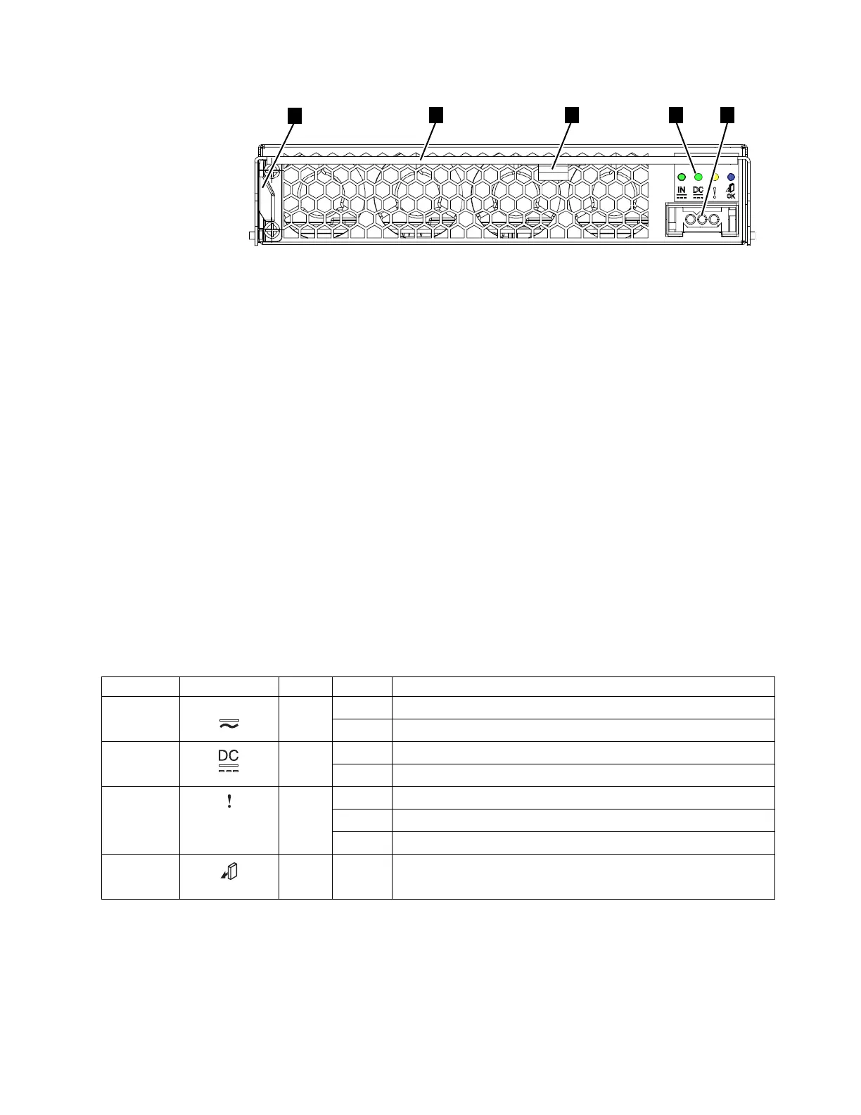
▌1▐ Release tab
▌2▐ Handle
▌3▐ Power supply LED indicators
▌4▐ Direct current power connector
▌5▐ Cable retainer
Each power supply also contains fans that cool the enclosure. Cool air is drawn in
through the front of the enclosure. The air passes over the drives, node canisters,
and power supplies. The warmed air is ejected through the rear of each power
supply. For optimal cooling, do not obstruct the airflow and ensure that all
enclosure components or fillers are installed while the system is operational.
DC power supply LED indicators
Each power supply unit has four LED indicators. Table 8 summarizes their possible
values and meaning.
The LEDs have a comparable meaning to the LEDs on the AC power supply.
Problem diagnosis and service procedures are the same. For details, see “Powering
on the system” on page 153.
Table 8. DC power supply LED indicators
Name Label Color State Description
Input status
Green OFF No input power detected.
ON DC input power detected.
Output
status
Green OFF PSU is not providing DC output power.
ON PSU is providing DC output power.
Fault Amber OFF No fault detected.
ON PSU fault was detected.
BLINK PSU is being identified. A fault might have been detected.
(None)
Blue N/A Not used.
Connecting a DC power supply to a DC power source
An enclosure that is DC powered contains two DC power supply units (PSUs).
Each unit must be connected to a suitable -48V DC power source. To provide
redundancy in a power circuit failure, connect the two PSUs to different DC power
sources.
Figure 10. DC power supply unit connectors and indicators
Chapter 1. Before you begin the installation 13
 Loading...


