Table 7. Memory mirrored channel mode DIMM population sequence (continued)
Number of DIMMs
Number of installed
microprocessor DIMM connector
Seventh pair of DIMMs 2 13, 16
Eighth pair of DIMMs 2 21, 24
Ninth pair of DIMMs 2 14, 17
Tenth pair of DIMMs 2 20, 23
Eleventh pair of DIMMs 2 19, 22
Twelfth pair of DIMMs 2 15, 18
Note: DIMM connectors 3, 6, 7, 10, 15, 18, 19, and 22 are not used in memory mirrored
mode when UDIMMs are installed in the server.
When you install or remove DIMMs, the server configuration information changes.
When you restart the server, the system displays a message that indicates that the
memory configuration has changed.
Memory rank sparing
Sparing enables a failing rank to be replaced by ranks installed in an unoccupied
space. An unused spare rank on the channel can be used to copy the contents of a
failing rank on that channel. You can enable rank sparing memory in the Setup
utility, select System Settings → Memory. For more information, see “Using the
Setup utility” on page 120.
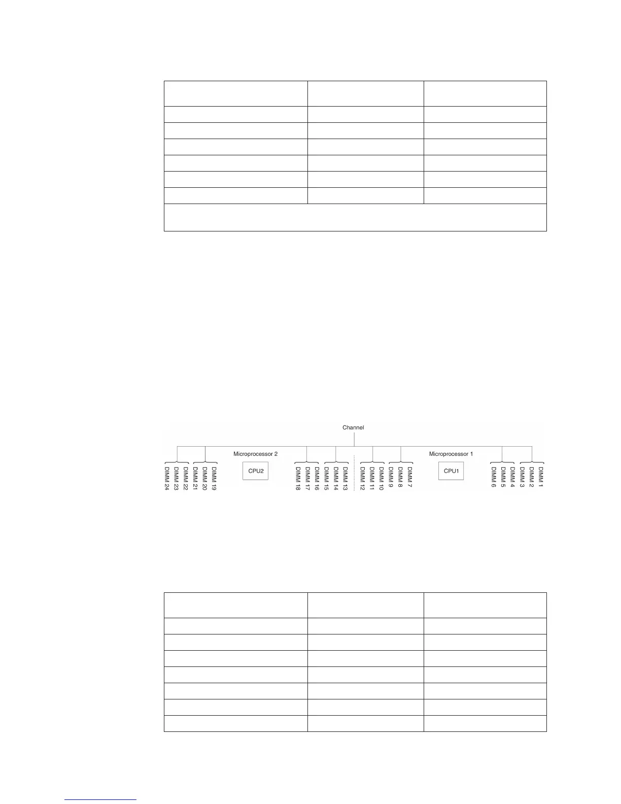
The following diagram lists the DIMM connectors on each memory channel.
You can install DIMMs for the microprocessor 2 once the microprocessor 2 is
installed. You do not need to wait until all of the DIMM connectors for
microprocessor 1 are filled. The following table shows the installation sequence for
memory rank sparing mode:
Table 8. Memory rank sparing mode DIMM population sequence
Number of DIMMs
Number of installed
microprocessor DIMM connector
First pair of DIMMs 1 1, 2
Second pair of DIMMs 1 4, 5
Third pair of DIMMs 1 8, 9
Fourth pair of DIMMs 1 11, 12
Fifth pair of DIMMs 1 7, 10
Sixth pair of DIMMs 1 3, 6
Seventh pair of DIMMs 2 13, 14
Figure 14. Connectors on each memory channel
82 IBM System x3500 M4 Type 7383: Installation and User’s Guide
 Loading...