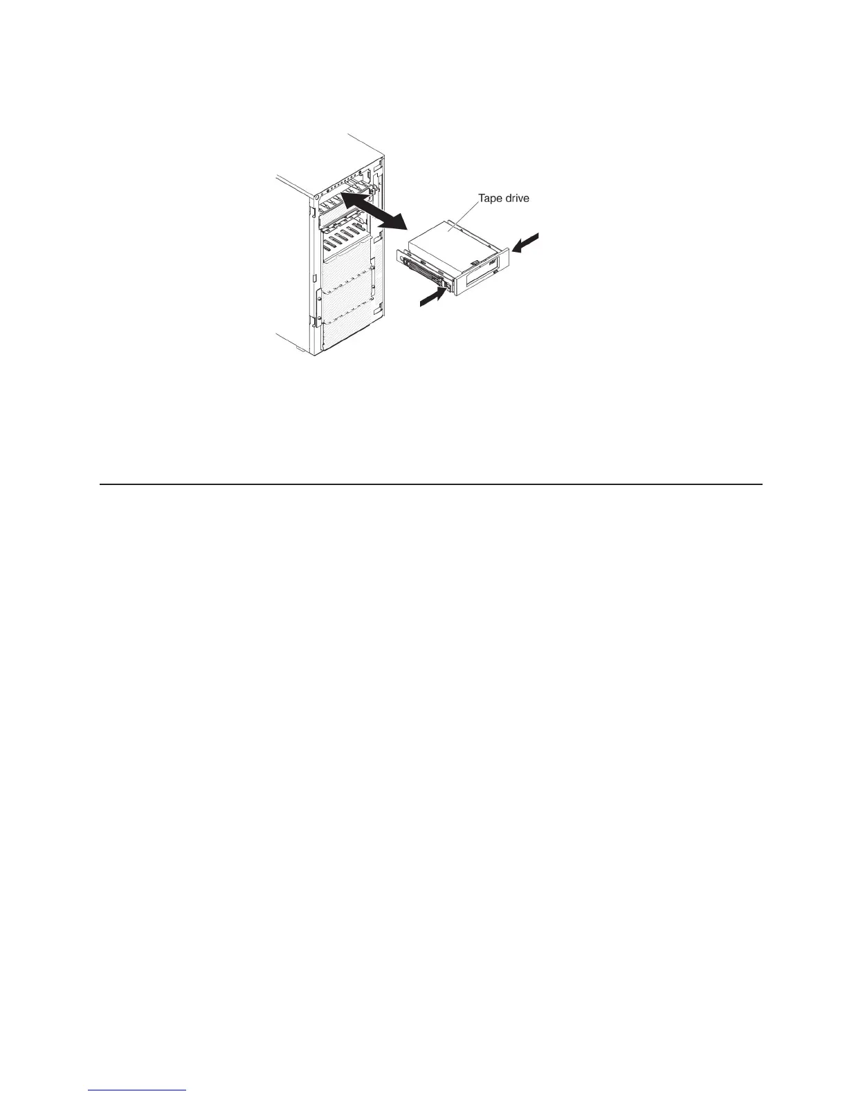
12. Align the rails on the tape drive with the guides in the drive bay; then, slide the
tape drive into the drive bay until the rails click into place.
13. Connect power and signal cables to the drive and the connectors on the
system board (see “Internal cable routing and connectors” on page 40 for more
information).
If you have other devices to install or remove, do so now. Otherwise, go to
“Completing the installation” on page 109.
Installing a memory module
The following notes describe the types of DIMMs that the server supports and other
information that you must consider when you install DIMMs.
v When you install or remove DIMMs, the server configuration information
changes. When you restart the server, the system displays a message that
indicates that the memory configuration has changed.
v The server supports only industry-standard double-data-rate 3 (DDR3), 800,
1066, 1333, or 1600 MHz, PC3-6400, PC3-8500, PC3-10600, or PC3-12800
registered or unbuffered, synchronous dynamic random-access memory
(SDRAM) dual inline memory modules (DIMMs) with error correcting code (ECC).
See http://www.ibm.com/servers/eserver/serverproven/compat/us/ for a list of
supported memory modules for the server.
– The specifications of a DDR3 DIMM are on a label on the DIMM, in the
following format.
ggggg eRxff PC3v-wwwwwm-aa-bb-ccd
where:
ggggg is the total capacity of the DIMM (for example, 1GB, 2GB, or 4GB)
eR is the number of ranks
1R = single-rank
2R = dual-rank
4R = quad-rank
xff is the device organization (bit width)
x4 = x4 organization (4 DQ lines per SDRAM)
x8 = x8 organization
x16 = x16 organization
v is the SDRAM and support component supply voltage (VDD)
Blank = 1.5 V specified
Chapter 2. Installing optional devices 77