5. Move the UEFI boot backup jumper (JP13) from pins 1 and 2 to pins 2 and 3
to enable the UEFI recovery mode.
6. Reinstall the server cover; then, reconnect all power cords.
7. Restart the server. The system begins the power-on self-test (POST).
8. Boot the server to an operating system that is supported by the firmware
update package that you downloaded.
9. Perform the firmware update by following the instructions that are in the
firmware update package readme file.
10. Turn off the server and disconnect all power cords and external cables, and
then remove the cover (see “Removing the cover” on page 126).
11. Move the UEFI boot backup jumper (JP13) from pins 2 and 3 back to the
primary position (pins 1 and 2).
12. Reinstall the cover (see “Replacing the cover” on page 127).
13. Reconnect the power cord and any cables that you removed.
14. Restart the server. The system begins the power-on self-test (POST). If this
does not recover the primary bank, continue with the following steps.
15. Remove the cover (see “Removing the cover” on page 126).
16. Reset the CMOS by removing the system battery (see “Removing the system
battery” on page 218).
17. Leave the system battery out of the server for approximately 5 to 15 minutes.
18. Reinstall the system battery (see “Replacing the system battery” on page 220).
19. Reinstall the cover (see “Replacing the cover” on page 127).
20. Reconnect the power cord and any cables that you removed.
21. Restart the server. The system begins the power-on self-test (POST).
22. If these recovery efforts fail, contact your IBM service representative for
support.
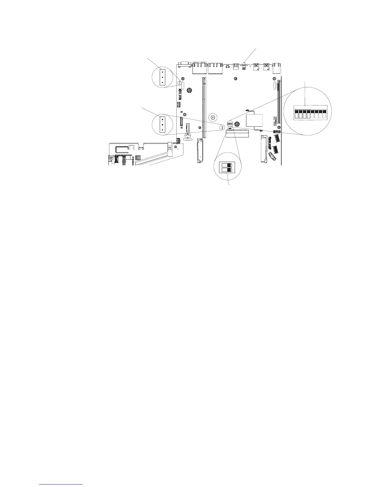
UEFI boot backup
jumper (J13)
System TPM physical
presence switch (SW11)
CMOS clear jumper (J11)
NMI button
1
2
SW3 switch
block
On
Off
483
7
2
6
1
5
1
2
3
1
2
3
On
Off
Figure 31. UEFI boot backup jumper (JP13) location
Chapter 3. Troubleshooting 107
 Loading...