Server controls, LEDs, and connectors
This section describes the controls, light-emitting diodes (LEDs), and connectors.
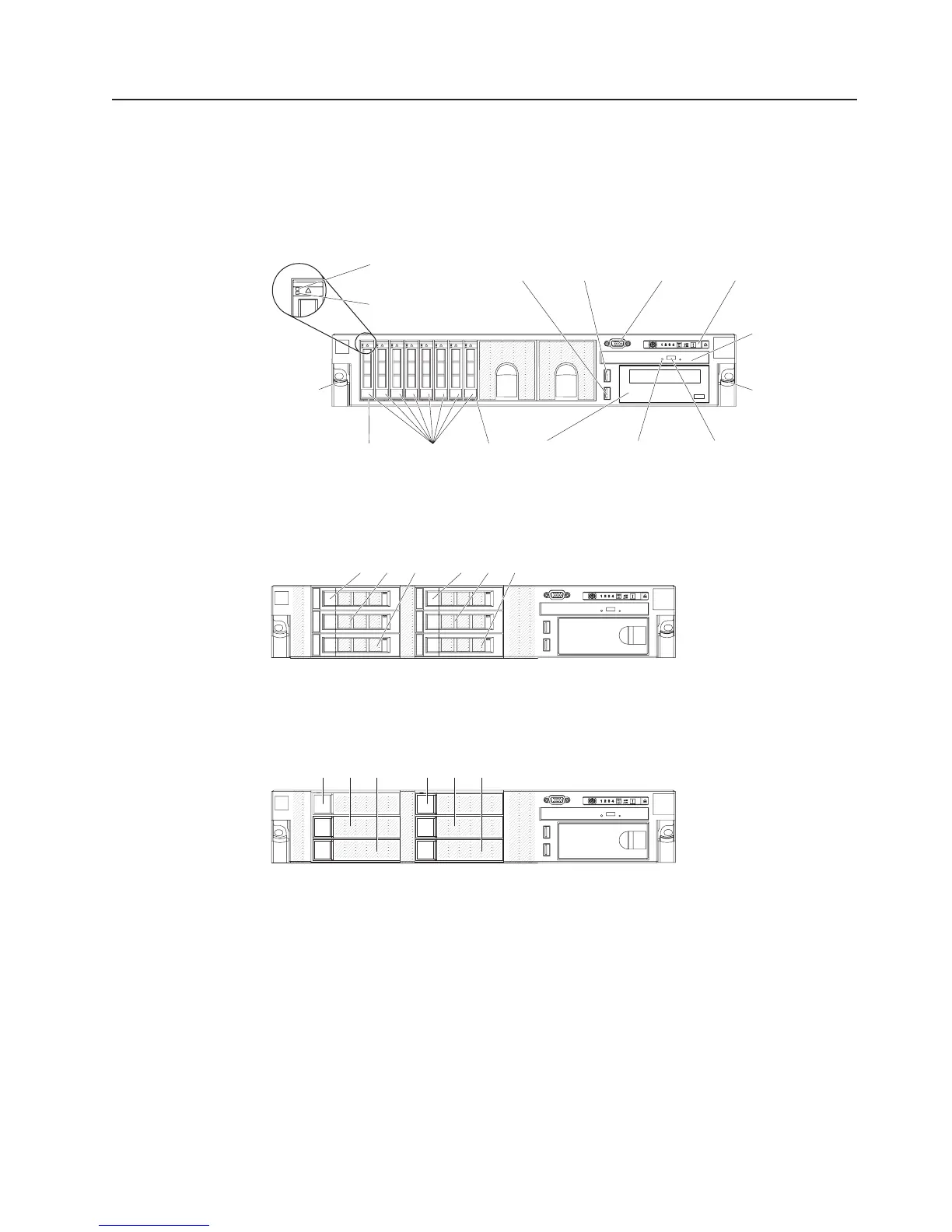
Front view
The following illustration shows the controls, LEDs, and connectors on the front of
the 2.5-inch SAS/SATA hot-swap hard disk drive server model.
Hard disk drive
activity LED (green)
Hard disk drive
status LED (amber)
Hard disk
drive bays
Rack
release
latch
Video
connector
USB 1
connector
USB 2
connector
Operator
information panel
CD/DVD
eject button
CD/DVD drive
activity LED
Rack
release
latch
CD/DVD drive
(optical drive)
Bay 7Bay 0
Tape drive
(optional)
The following illustration shows the 3.5-inch SAS/SATA hot-swap hard disk drive
server model.
SAS hard disk
drive bays
012 345
The following illustration shows the 3.5-inch SATA simple-swap hard disk drive
server model.
SATA hard disk
drive bays
012 345
Hard disk drive activity LED: Each hard disk drive has an activity LED. When this
LED is flashing, it indicates that the drive is in use.
Hard disk drive status LED: Each hard disk drive has a status LED. When this
LED is lit, it indicates that the drive has failed. When this LED is flashing slowly
(one flash per second), it indicates that the drive is being rebuilt as part of a RAID
configuration. When the LED is flashing rapidly (three flashes per second), it
indicates that the controller is identifying the drive.
Video connector: Connect a monitor to this connector. The video connectors on
the front and rear of the server can be used simultaneously.
Chapter 2. Introduction 9
 Loading...


