Memory rank sparing
The memory rank sparing feature disables the failed memory from the system
configuration and activates a rank sparing DIMM to replace the failed active DIMM.
You can enable rank sparing memory in the Setup utility, select System Settings →
Memory. For more information, see “Using the Setup utility” on page 145. When
you use the memory rank sparing feature, consider the following information:
v The memory rank sparing feature is supported on server models with an Intel
Xeon
™
5600 series microprocessor.
v The maximum available memory is reduced when memory rank sparing mode is
enabled.
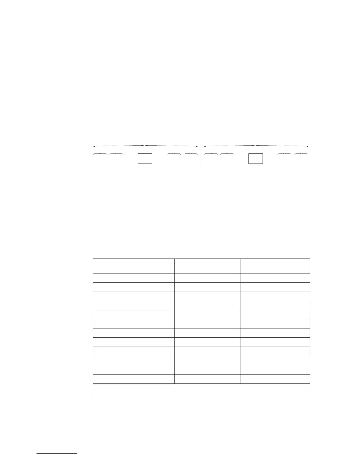
The following diagram lists the DIMM connectors on each memory channel.
Follow the installation sequence for rank sparing mode:
v Install at least one quad-rank DIMM in a channel.
v Install at least two single-rank or dual-rank DIMMs in a channel.
You can install DIMMs for the microprocessor 2 once the microprocessor 2 is
installed. You do not need to wait until all of the DIMM connectors for
microprocessor 1 are filled. The following table shows the installation sequence for
memory rank sparing mode:
Table 10. Memory rank sparing mode DIMM population sequence
Number of DIMMs
Number of installed
microprocessor DIMM connector
First pair of DIMMs 1 1, 2
Second pair of DIMMs 1 4, 5
Third pair of DIMMs 1 8, 9
Fourth pair of DIMMs 1 11, 12
Fifth pair of DIMMs 1 7, 10
Sixth pair of DIMMs 1 3, 6
Seventh pair of DIMMs 2 13, 14
Eighth pair of DIMMs 2 16, 17
Ninth pair of DIMMs 2 20, 21
Tenth pair of DIMMs 2 23, 24
Eleventh pair of DIMMs 2 19, 22
Twelfth pair of DIMMs 2 15, 18
Note: DIMM connectors 3, 6, 7, 10, 15, 18, 19, and 22 are not used in memory rank
sparing mode when UDIMMs are installed in the server.
DIMM 3
DIMM 9
DIMM 6
DIMM 12
DIMM 2
DIMM 8
DIMM 5
DIMM 11
DIMM 1
DIMM 7
DIMM 4
DIMM 10
CH1Ch2 CH0Ch3
Microprocessor 1
CPU1
DIMM 15
DIMM 21
DIMM 18
DIMM 24
DIMM 14
DIMM 20
DIMM 17
DIMM 23
DIMM 13
DIMM 19
DIMM 16
DIMM 22
CH1Ch2 CH0Ch3
Microprocessor 2
CPU2
Figure 2. Connectors on each memory channel
112 System x3650 M4 Type 7915: Installation and User’s Guide
 Loading...


