System-board switches and jumpers
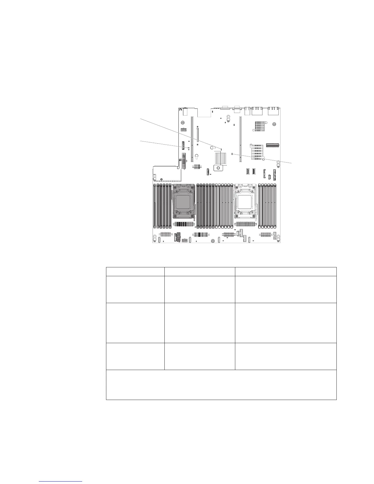
The following illustration shows the location and description of the switches and
jumpers.
Note: If there is a clear protective sticker on the top of the switch blocks, you must
remove and discard it to access the switches.
The default positions for the UEFI and the IMM recovery jumpers are pins 1 and 2.
CMOS clear
jumper (JP1)
UEFI boot backup
jumper(JP2)
System TPM physical
presence jumper(JP20)
The following table describes the jumpers on the system board.
Table 3. System board jumpers
Jumper number Jumper name Jumper setting
JP1 CMOS clear jumper
v Pins 1 and 2: Normal (default).
v Pins 2 and 3: Clears the real-time
clock (RTC) registry.
JP2 UEFI boot backup jumper
v Pins 1 and 2: Normal (default).
Loads the primary server firmware
ROM page.
v Pins 2 and 3: Loads the secondary
(backup) server firmware ROM page.
JP20 System TPM physical
presence jumper
v Pins 1 and 2: Normal (default).
v Pins 2 and 3: Indicates a physical
presence to the system TPM.
Note: Changing the position of the UEFI boot recovery jumper from pins 1 and 2 to pins 2
and 3 before the server is turned on alters which flash ROM page is loaded. Do not change
the jumper pin position after the server is turned on. This can cause an unpredictable
problem.
The following table describes the functions of the SW3 switch block on the system
board.
Chapter 2. Installing optional devices 35
 Loading...


