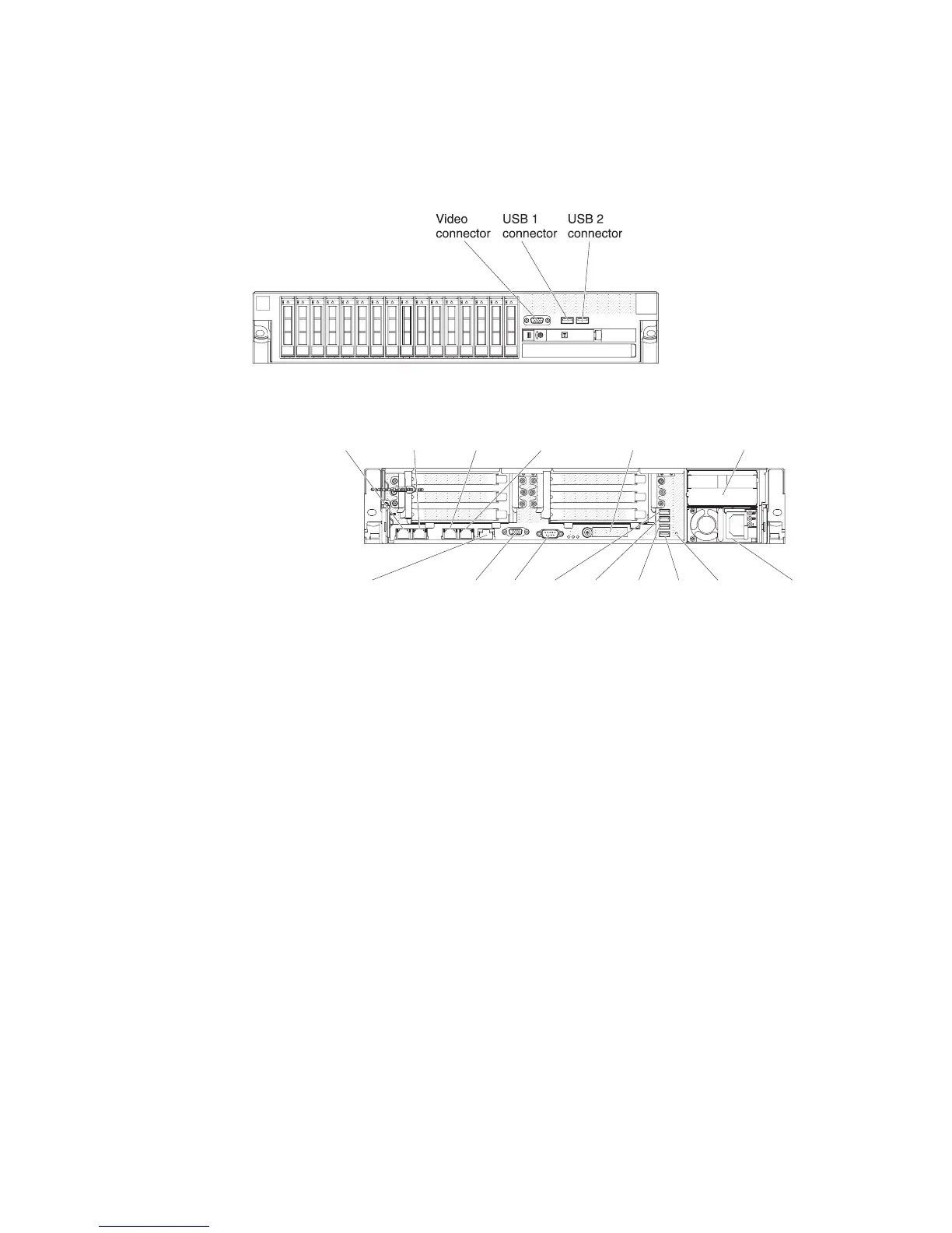
Connecting the external cables
The following illustrations show the locations of the input and output connectors on
the front and rear of the server.
Front view
Rear view
Video Serial
Power supply 1
Power supply 2
Ethernet1
(shared system
management ethernet)
Ethernet2 Ethernet3 Ethernet4
System-management
(ethernet)(dedicated)
10G ethernet
(with optional
10G ethernet card)
USB5USB3 USB4 USB6 NMI
button
See the documentation that comes with any external devices for additional cabling
instructions. It might be easier for you to route cables before you connect the
devices to the server.
If the server comes with an installed operating system, see the documentation that
comes with the operating system for additional cabling instructions.
138 System x3650 M4 Type 7915: Installation and User’s Guide
 Loading...


