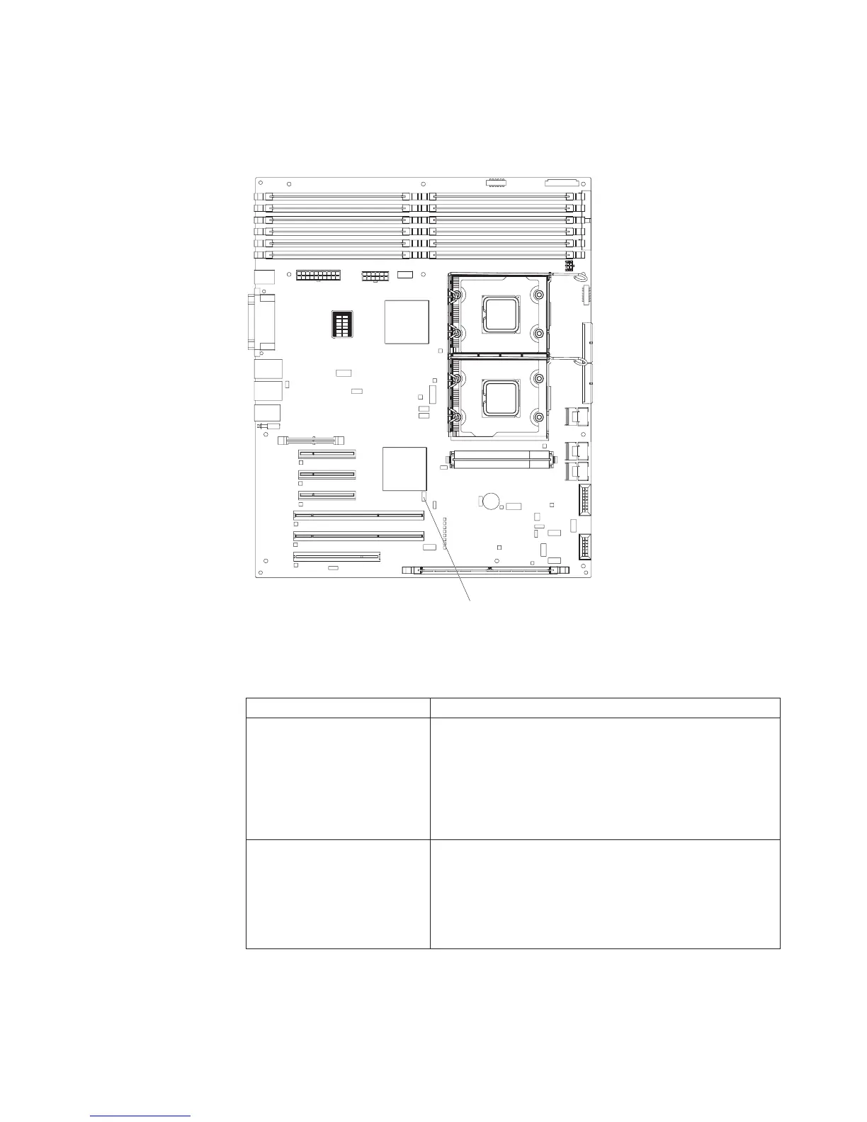
System-board switches
The following illustration shows the SW4 switch (Boot block/Clear CMOS) on the
system board.
1
2
3
4
5
6
7
8
9
10
11
12
DIMM LEDs
SW4 (Boot block/Clear CMOS)
The following table describes the function of each pin on the SW4 switch (Boot
block/Clear CMOS) on the system board.
Table 3. System board SW4 switch
Switch pin number Description
1 Boot block:
v When this switch is on 1, this is normal mode.
v When this switch is toggled to On, this enables the
system to recover if the BIOS code becomes damaged.
See
the Problem Determination and Service Guide for
information about recovering from a BIOS update failure.
2 Clear CMOS:
v When this switch is on 2, this is normal mode. This
keeps the CMOS data.
v When this switch is toggled to On, this clears the CMOS
data, which clears the power-on password and
administrator password.
Chapter 2. Installing options 19
 Loading...