Connecting the cables
Attention: To prevent damage to equipment, connect the power cords last.
If the server cables and connector panel have color-coded connections, match the
color of the cable end with the color of the connector. For example, match a blue
cable end with a blue panel connector, a red cable end with a red connector, and
so on.
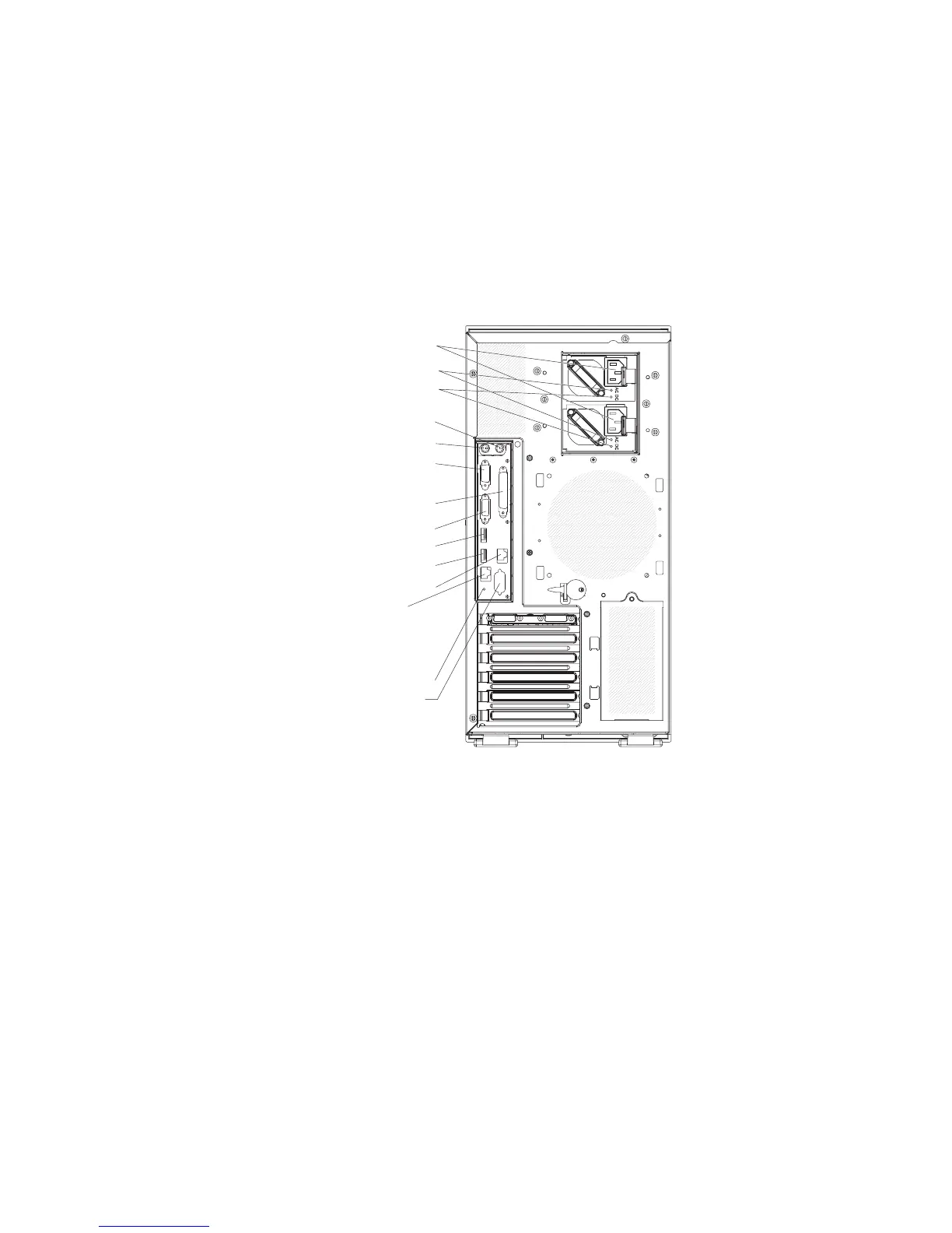
The following illustration shows the input/output (I/O) connectors on the rear of the
hot-swap power supply models with optional redundant power.
Mouse
Keyboard
Serial 1
(COM 1)
Video
Parallel
USB 4
(RJ45) Ethernet 10/100/1000
(RJ45) Ethernet 10/100
(for Remote Supervisor Adapter II
SlimLine)
USB 3
NMI button
AC power LEDs
DCpower LEDs
Power cords
Serial 2
(COM 2)
The following illustration shows the input/output (I/O) connectors on the rear of the
non-hot-swap power supply models.
Chapter 2. Installing options 71
 Loading...