v DIMMs in the server must be the same type (RDIMM, UDIMM, or LRDIMM) to
ensure that the server will operate correctly.
v When you install one quad-rank DIMM in a channel, install it in the DIMM
connector furthest away from the microprocessor.
Notes:
1. You can install DIMMs for microprocessor 2 as soon as you install
microprocessor 2; you do not have to wait until all of the DIMM slots for
microprocessor 1 are filled.
2. DIMM slots 13-24 are reserved for microprocessor 2; thus, DIMM slots 13-24 are
enabled when microprocessor 2 is installed.
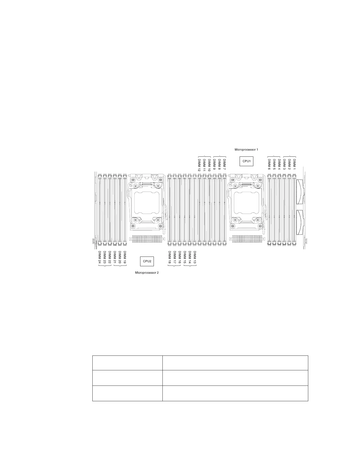
The following illustration shows the location of the DIMM connectors on the
system board.
DIMM installation sequence
Depending on the server model, the server may come with a minimum of one 2
GB or 4 GB DIMM installed in slot 1. When you install additional DIMMs, install
them in the order shown in the following table to optimize system performance.
In general, all three channels on the memory interface for each microprocessor can
be populated in any order and have no matching requirements.
Table 6. Normal mode DIMM installation sequence
Number of installed
microprocessor DIMM connector population sequence
One microprocessor
installed
1, 4, 9, 12, 2, 5, 8, 11, 3, 6, 7, 10
Two microprocessors
installed
1, 13, 4, 16, 9, 21, 12, 24, 2, 14, 5, 17, 8, 20, 11, 23, 3, 15, 6, 18,
7, 19, 10, 22
Figure 35. DIMM connectors location
52 IBM System x3550 M4 Type 7914: Installation and Service Guide
 Loading...