• RX AF CIRCUITS
• TX AF CIRCUITS
• MODULATION CIRCUITS
3 - 3
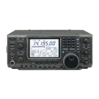
RX AF CIRCUITS (CONNECT UNIT)
• AUDIO OUTPUT FROM THE SP/HEADPHONES
The AF signal from the demodulator circuits is applied to
the AF AMP (IC221), through the squelch gate (Q231).
The amplifi ed AF signal is applied to the Voltage Controlled
Amplifi er (VCA; IC301) to be adjusted in level (=audio output
level).
The level-adjusted AF signal is applied to the AF power AMP
(IC351), through the mute SW (Q331) and AF SW (Q321).
The amplified AF signal is passed through the AF mute
switch (Q371), and then applied to the internal speaker or
external speaker jack (J101), or the amplified AF signal is
applied to the headphones jack (JACK BORD: J2).
3-2 TRANSMITTER CIRCUITS
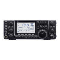
TX AF CIRCUITS (MAIN UNIT)
The audio signal from the microphone (MIC signal) is
applied to the MAIN UNIT, through the MICROPHONE
CONNECTOR (MIC BOARD; J1), and then applied to the
Voltage Controlled Amplifi er (VCA; IC3401).
The applied MIC signal is amplified by the MIC AMP, and
adjusted in level (=MIC gain) by the VCA circuit.
The level-adjusted MIC signal is passed through the MIC
line SW (IC3421), amplifi ed by the AF AMP (IC3452), and
then applied to the modulation circuits, through the two LPFs
(IC3452).
The MIC signal from the accessory socket [ACC1] on the
rear panel, is directly applied to the AF AMP (IC3452),
through the MIC line SW (IC3421).
The amplified MIC signal is applied to the modulation
circuits.
From the
modulator
circuits
AMP
IC221
VCA
J101
SP1
J2(JACK UNIT)
SQL
GATE
Q231
[PHONES]
AMP
IC301
Internal
speaker
AF
AMP
IC351
Q321
AF
SW
Q371
AF
SW
AF
AMP
Q326
Q331
MUTE
SW
CONNECT UNIT
[EXT-SP]
AF
SW
MIC
AMP
IC3401
AMP
VCA
VCA
AMP
IC3452
LPF
IC3452
MIC
LPF
IC3452
IC3421
To the modulation
circuits
FRONT PANEL
CONNECT UNIT
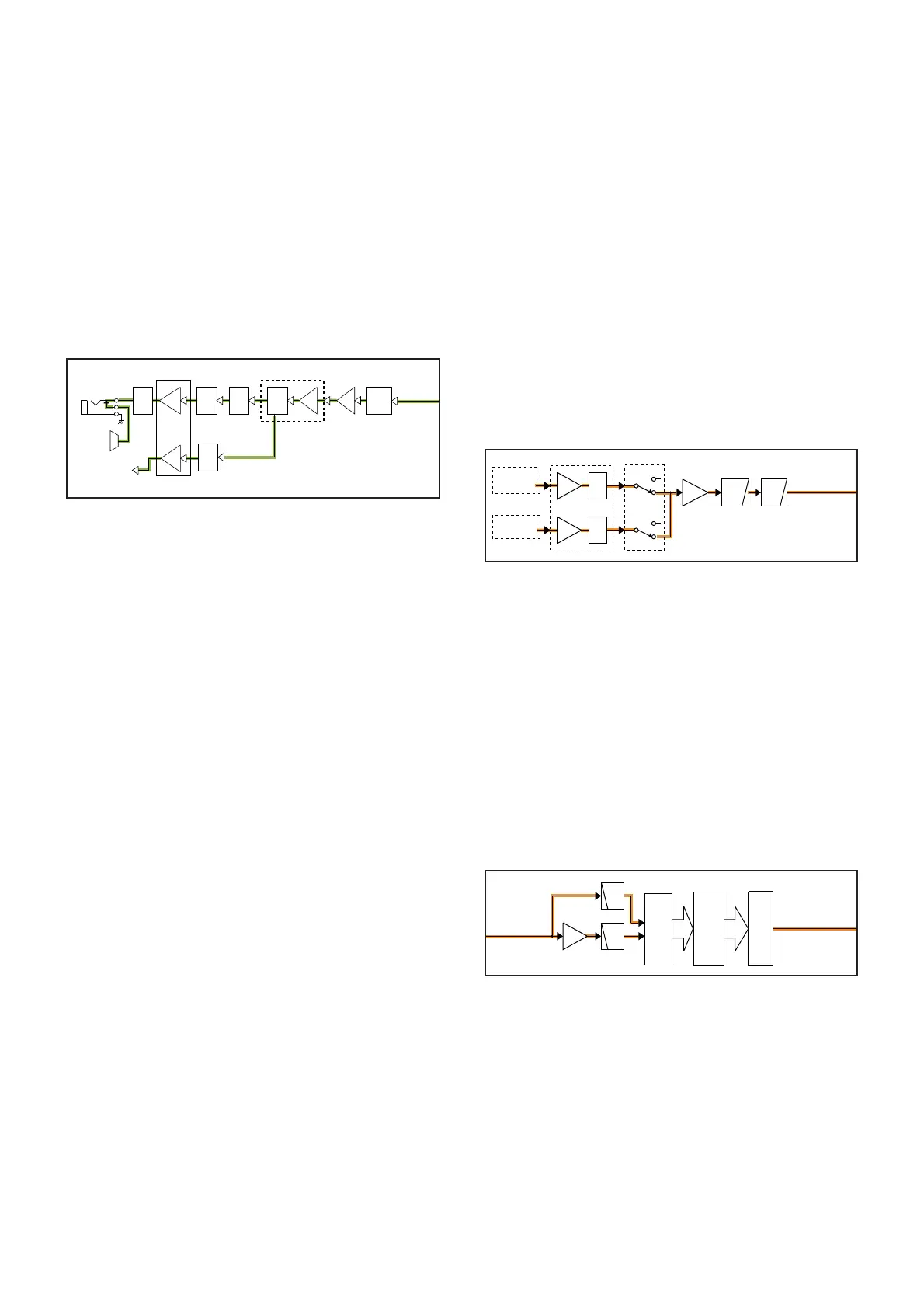
MODULATION CIRCUITS (MAIN UNIT)
The MIC signal from the TX AF circuits is passed through
the Balance-Unbalance converter (Balun; IC4401, IC4402),
and then applied to the CODEC (IC4461), to be converted
into digital audio signal.
The converted digital audio signal is applied to the DSP
(IC4001), and processed and modulated.
The modulation signal is converted into analog audio signal
by the CODEC (IC4651), and then applied to the 3rd TX IF
circuits as the 3rd TX IF signal.
BUFF
IC4401
LPF
IC4402
LPF
IC4402
To the 1st TX IF
circuits
From the TX AF
circuits
CODEC
CODEC
IC4461
DSP_MOD IN
IC4001
DSP
IC4651
 Loading...