3 - 4
• 3RD TX IF AND 2ND TX IF CIRCUITS
• BPF CIRCUITS
• 1ST TX IF CIRCUITS
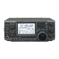
1ST TX IF CIRCUITS (RF-A UNIT)
The 1st TX IF signal from the 2nd TX IF circuits is passed
through the 1st TX IF filter (FI911) to remove unwanted
signals. The fi ltered signal is amplifi ed by the IF AMP (Q611),
and then applied to the 1st TX mixer (D651), through the
LPF.
The 1st TX IF signal is mixed with the 1st TX LO signal from
the PLL UNIT, resulting in the TX signal (TX frequency itself).
The converted TX signal is passed through the LPF, and
amplifi ed by the AMP (IC601), and then applied to the BPF
circuits.
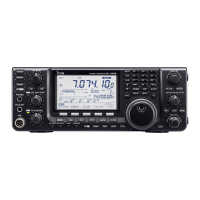
BPF CIRCUITS
The TX signal from the 1st TX IF circuits is passed through
an LPF or one of BPFs, depending on the transmitting
frequency, to remove unwanted signals contained in the TX
signal.
The fi ltered TX signal is amplifi ed by the YGR AMP (IC201),
and then applied to the PA-A UNIT, through the BPF.
D651
IF
AMP
Q611
BPF
XTAL
64.455 MHz(BW=15 kHz)
FI911
From the
2nd TX IF
circuits
To the
BPF
circuits
LPF LPF
IF
AMP
IC601
LO
AMP
Q811
LPF
LPF
LPF
RF-A UNIT
64.485~
124.455 MHz
1st TX LO
YGR
AMP
IC201
BPF
BPF
BPF
BPF
BPF
BPF
BPF
HPF
BPF
LPF
BPF
BPF
From the
1st TX IF
circuits
To the
TX amplifier
circuits
1.6-2.0 MHz
4.0-8.0 MHz
50.0-54.0 MHz
30.0-50.0 MHz
11.0-15.0 MHz
8.0-11.0 MHz
54.0-60.0 MHz
2.0-4.0 MHz
15.0-22.0 MHz
22.0-30.0 MHz
BPF UNIT
0.03-1.6 MHz
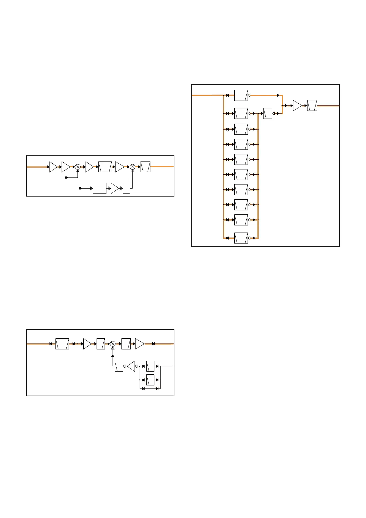
3RD TX IF AND 2ND TX IF CIRCUITS (MAIN UNIT)
The 3rd TX IF signal from the modulation circuits is amplifi ed
by two AMPs (IC4661 and IC3601), and then applied to
the 3rd TX mixer (IC3621) to be mixed with the 3rd TX LO
signal from the PLL UNIT, resulting in the 455 kHz 2nd TX IF
signal.
The converted 2nd TX IF signal is amplifi ed by the IF AMP
(Q3631), and then passed though the 2nd TX fi lter (FI3641).
The fi ltered 2nd TX IF signal is amplifi ed by the 2nd TX IF
AMP (Q3651), and then applied to the 2nd TX mixer (D3671).
The 2nd TX IF signal is mixed with the 64 MHz 2nd TX LO
signal from the PLL UNIT, resulting in the 64.455 MHz 1st
TX IF signal.
The 1st TX IF signal is applied to the 1st TX IF circuits on
the RF-A UNIT.
ATT
T2LO
BPF
CERAMIC
455kHz(BW=20k)
FI3641
T3LO
AMP
IC3601
LO
AMP
IC3675
IC3621
BPF
64.455 MHz
D3671
ATT
IF
AMP
Q3651
IF
AMP
Q3631
AMP
IC4661
From the
modulation
circuits
To the
1st TX IF
circuits
491 kHz
From the PLL UNIT
From the PLL UNIT
64 MHz
 Loading...