3 - 6
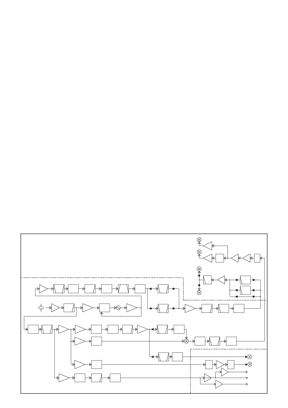
3-3 FREQUENCY SYNTHESIZER (PLL UNIT)
REFERENCE FREQUENCY OSCILLATOR CIRCUIT
The crystal oscillator (X151) generates the 32 MHz
reference frequency signal. This reference signal is applied
to the Local Oscillator (LO) circuits, through the buffer (Q151)
and LPF (L153, C156–158).
3RD TX LO CIRCUIT
The 32 MHz reference signal from the crystal oscillator
(X151) is doubled by t
he doubler (Q551, L551, L552),
resulting in the
64 MHz reference clock signal. Using the
64 MHz reference clock signal, the 491 kHz 3rd TX LO
signal is directly generated by 10-bit DDS (IC702) and D/A
converter (R703–R722). The generated 491 kHz 3rd TX LO
signal is passed through the LPF (L702, C713, C715), buffer
(Q701), LO SW (D851), BPF (L851–L853, C851, C853,
C855, C856, C858), and then applied to the MAIN UNIT.
2ND TX LO CIRCUIT
The 32 MHz reference signal from the reference frequency
oscillator circuit is doubled by the doubler (Q551, L551,
L552) to extract the 64 MHz of 2nd harmonic component. The
64 MHz signal is applied to the MAIN UNIT as the 2nd TX LO
signal, through the buffers (Q552 and Q571).
The 2nd TX LO signal is amplified by the LO AMP (MAIN
UNIT: IC3675), and then applied to the 2nd TX mixer (MAIN
UNIT: D3671).
2ND RX LO CIRCUIT
The 64 MHz reference signal from the buffer (Q552) and the
491 kHz signal from the 3rd TX LO circuit is mixed by the
2nd RX LO mixer (D951), to generate the 2nd RX LO signal.
The 2nd RX LO signal is fi ltered by the crystal fi lter (FI981),
and then applied to the RF-A UNIT as the 2nd RX LO signal.
The 2nd RX LO signals which are 90 degrees phase-shifted
from each other, is applied to the 2nd IF mixers (D1101 and
D1102), through the buffers (IC1121).
1ST RX LO/TX LO CIRCUITS
The 32 MHz reference signal from the reference frequency
oscillator circuit is amplifi ed by Q201, and applied to the PLL
IC (IC201) as the reference frequency signal. The PLL IC
(IC201) generates the 388.5 MHz master clock signal, using
the applied 32 MHz reference signal as the reference.
The generated 388.5 MHz master clock signal is
passed through the buffer (Q301) and BPF (L301–L304,
C305–C312), and then applied to the DDS IC (IC351).
Using the applied DDS master clock signal as the referece,
the DDS IC generates the 1st RX/TX LO signal. The
generated 1st RX/TX LO signal is passed through the
LPF (L381, C381, C382), MCF notch fileter (FI401), BPF
(L421–L423, C421–C428 or L451–L453, C451–C458, C462;
depending on the operating frequency), and amplifi ed by the
LO AMP (IC501). The amplifi ed signal is applied to the RF-A
UNIT, through the LPF (L502, L503, C504–C509), HPF
(L504, C510–512).
The 1st RX/TX LO signal is passed through the harmonic
filter (RF-A UNIT; L868–L870, C872–C876 or L861–L864,
C866–C870 or L871, C879, C880), and amplified by the
LO AMP (Q811), and then applied to the 1st RX mixer
(Q721–Q724) or 1st TX mixer (D651), through the LPF
(L831–L833, C831–C836) and LO SW (D851, D852).
D1101
D1102
2nd RX IF mixer
2nd RX IF mixer
1st RX IF mixer
1st TX IF mixer
D651
Q721/Q722/Q723/Q724
LO
AMP
Q811
LPF
X151
32MHz
Reference frequency
signal oscillator
LPFBPF
64MHz
D/AX2
KTC3880
Q551
PLL
IC
IC201
REF=500kHz
D951
AMP
Q201
AM P
SN74AHC1G04
IC701
BPF
XTAL
64.491MHz
FI981
BUFF
Q701
ATT
BUFF
Q271
BUFF
Q151
ATT ATTATT
BPF
491kHz
Q251
DDS
IC702
LPF
BUFF
Q571
ATT
CODEC_CLK
AM P
IC661
BUFF
Q301
BRF
FI401
64.455MHz
LPF
DD S
IC351
ATTHPF
ATT
BPF
BPFATTBPF
AM P
IC 5 0 1
LPF
BUFF
IC1121
BUFF
IC1121
LO
AMP
Q1141
BUFF
IC1121
BPF
491kHz
T3Lo
1st TX/RX Lo
1st RX LO Lo
1st TX LO Lo
2nd RX Lo
ATT
90deg
BUFF
KTC3880
Q552
P-CLK
IC662
BUFF
Q901
ATT
ATTLPF
LPF
LPF
MCLK
RF-A UNIT
PLL UNIT
MAIN UNIT
86.455-124.455MHz
64.485-86.455MHz
388.5MHz
ATT
T2LO
LO
AMP
IC3675
IC3621
D3671
ATT
3rd TX mixer
2nd TX mixer
491kHz
64MHz
IC3913
AM P
AM P
AM P
IC3913
IC3955
DSP_CLK24
MCLK24M
MCLK24M
•
FREQUENCY SYNTHESIZER
CIRCUITS
 Loading...