3 - 8
Pin
No.
Line
Name
Description I/O
1 CNT2V
LCD contrast control. (segement area)
(1–2.3 V)
O
2 CNT1V
LCD contrast control. (dot area)
(1–2.3 V)
O
10 FRES
Front CPU Reset.
L=Reset.
I
19 RITDBK [RIT/
TX] dial phase-B. I
20 RITDAK [RIT/
TX] dial phase-A. I
21 MAINDAK [MAIN] dial phase-A. I
22 MAINDBK [MAIN] dial phase-B. I
23 TDS
TX LED control.
H=Lights. (While transmitting)
O
24 BKLV LCD backlight control. (PWM) O
29 DTXD UART port (TX) O
30 DRXD UART port (RX) I
33 LTXD
Data output (UART) for the communication
with the main CPU.
O
34 LRXD
Data input (UART) for the communication with
the main CPU.
I
35 DOTK Ele-key input. (Dot) I
36 DSHK Ele-key input. (Dash) I
37 PHNK
Headphones connection detect.
H=Connected.
I
38 NOTK [NOTCH] input. (Pull-up) I
40 LOCKK [LOCK] input. (Pull-up) I
43 PBCLK [PBT-CLK] input. (Pull-up) I
45 RITCLK [CLEAR] input. (Pull-up) I
46 DTXK [
TX] input. (Pull-up) I
47 FILK [FILTER] input. (Pull-up) I
48 XFCK [XFC] input. (Pull-up) I
49 MENUK [MENU] input. (Pull-up) I
50 RITK [RIT] input. (Pull-up) I
51 F5K [F-5] input. (Pull-up) I
52 F4K [F-4] input. (Pull-up) I
53 F3K [F-3] input. (Pull-up) I
54 F2K [F-2] input. (Pull-up) I
55 F1K [F-1] input. (Pull-up) I
56 NBK [NB] input. (Pull-up) I
57 NRK [NR] input. (Pull-up) I
58 ANTK [ANT] input. (Pull-up) I
59 TUNK [TUNER] input. (Pull-up) I
61 TRAK [TRANSMIT] input. (Pull-up) I
63–
70
LD7–LD0 LCD segment ports. O
83 PBT2BK [PBT] outer dial phase-B. I
84 PBT2AK [PBT] outer dial phase-A. I
85 PBT1BK [PBT] inner dial phase-B. I
86 PBT1AK [PBT] inner dial phase-A. I
88 PITCHL [CW PITCH] dial input. I
90 NRL [NR] dial input. I
91 NOTL [NOTCH] dial input. I
92 MUDL [MIC] Up/Down input. I
98–
100
ASL2–
ASL0
Analog SW (CD4501) control. O
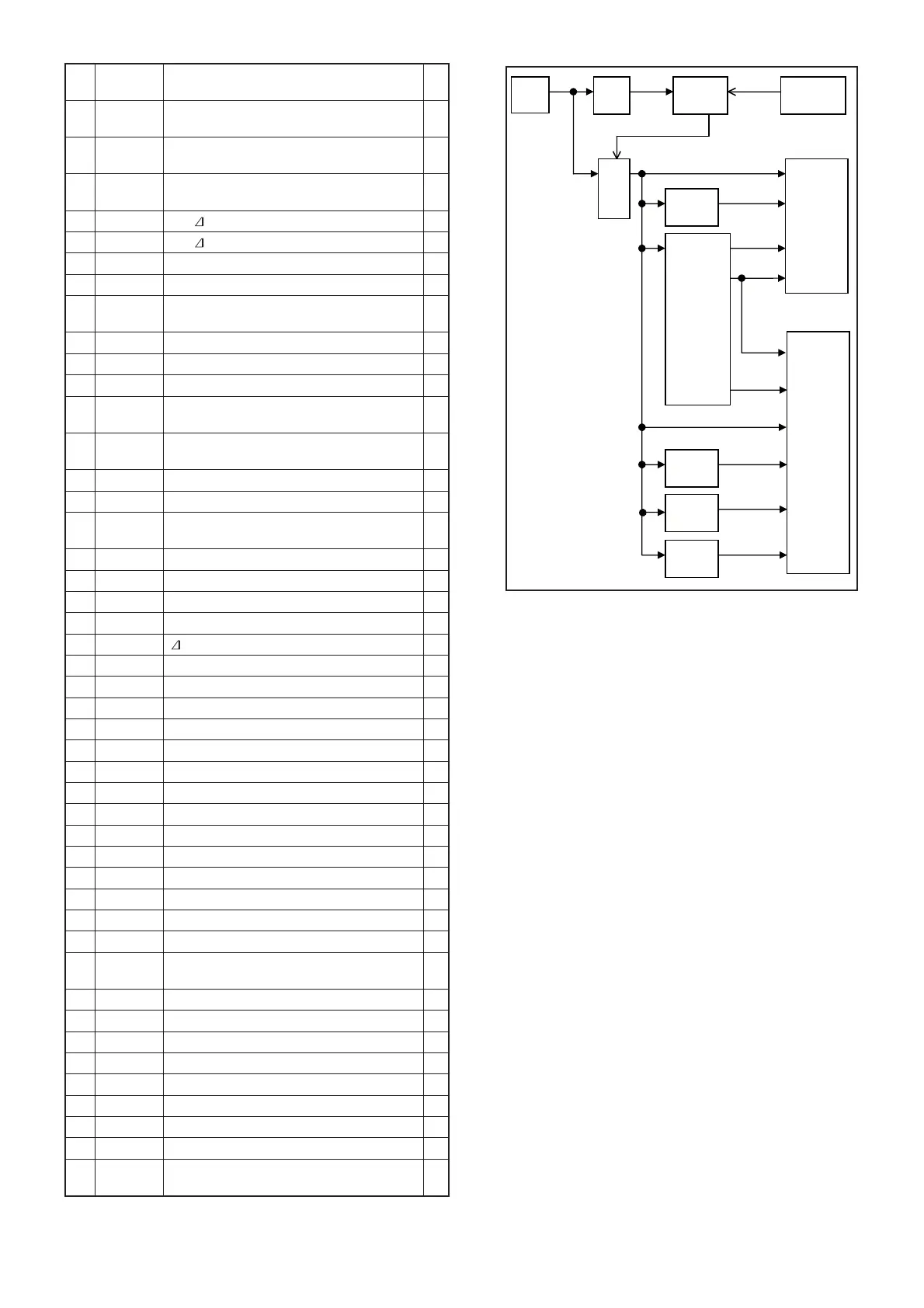
• FRONT CPU (DISPLAY BOARD: IC401)
FRONT
POWER SW
DC-IN
13.8V
FRONT
CPU
DC-DC
+3.3V
+1.2V
–8V
+3.3V
+1.2V
+13.8V
LOGIC
CIRCUITS
+8V
REG
+5V
REG
H3.3V
REG
SW
+8V
DC-DC
–12V
+5V
H14V
H3.3V
ANALOG
CIRCUITS
+3.3V
“PWRK ”
HV
“PWRS”
–8V
+5V
REG
+5V
3-5 VOLTAGE BLOCK DIAGRAM
 Loading...