11Esprit - Installation and Servicing
GENERAL
General
1. The installation must comply with all relevant national and
local regulations.
2. The installation should be designed to work with flow
temperatures of up to 82
o
C.
3. All components of the system must be suitable for a working
pressure of 3 bar and temperature of 110
o
C. Extra care should
be taken in making all connections so that the risk of leakage
is minimised.
The following components are incorporated within the
appliance:
a. Circulating pump.
b. Safety valve, with a non-adjustable preset lift pressure of
3 bar.
c. Pressure gauge, covering a range of 0 to 6 bar.
d. An 8-litre expansion vessel, with an initial charge pressure
of 1.0 bar.
4. 'Make-up' Water. Provision must be made for replacing
water loss from the system, either :
a. From a manually filled 'make-up' vessel with a readily
visible water level. The vessel should be mounted at
least 150mm above the highest point of the system and
be connected through a non-return valve to the system,
fitted at least 150mm below the 'make-up' vessel on the
return side of the radiators.
Notes
a. The method of filling, refilling, topping up or flushing
sealed primary hot water circuits from the mains via a
temporary hose connection is only allowed if acceptable
to the local water authority.
b. Antifreeze fluid, corrosion and scale inhibitor fluids
suitable for use with boilers having aluminium heat
exchangers may be used in the central heating system.
Advice should be sought from a local water treatment
company.
BOILER CONTROL INTERLOCKS
Ideal Stelrad Group recommend that heating systems
utilising full thermostatic radiator valve control of temperature
in individual rooms should also be fitted with a room
thermostat controlling the temperature in a space served by
radiators not fitted with such a valve as stated in BS. 5449.
Central heating system controls should be installed to
ensure the boiler is switched off when there is no demand
for heating or hot water.
When thermostatic radiator valves are used, the space
heating temperature control over a living / dining area or
hallway having a heating requirement of at least 10% of the
boiler heat output should be achieved using a room
thermostat, whilst other rooms are individually controlled by
thermostatic radiator valves. However, if the system employs
thermostatic radiator valves on all radiators, or two port
valves without end switches, then a bypass circuit is
incorporated within the boiler to ensure a flow of water
should all valves be in the closed position.
ELECTRICAL SUPPLY
WARNING.
This appliance must be earthed.
Wiring external to the appliance MUST be in accordance with
the current I.E.E. (BS.7671) Wiring Regulations and any local
regulations which apply. For IE reference should be made to
the current ETCI rules for electrical installations.
The point of connection to the mains should be readily
accessible and adjacent to the boiler.
N.B. THE FAN VOLTAGE IS 325VDC
CONDENSATE DRAIN Refer to Frames 21 & 49.
A condensate drain is provided on the boiler. This drain must
be connected to a drainage point on site. All pipework and
fittings in the condensate drainage system MUST be made of
plastic - no other materials may be used.
IMPORTANT.
Any external runs must be insulated.
The drain outlet on the boiler is standard 21.5mm (3/4”)
overflow pipe.
3
SYSTEM REQUIREMENTS - Central Heating
or
b. Where access to a 'make-up' vessel would be difficult,
by pre-pressurisation of the system.
The maximum cold water capacity of the system
should not exceed 143 litres, if not pressurized.
However, if the system is to be pressurized, the
efficiency of the expansion vessel will be reduced and
a larger vessel (or smaller system volume) may be
necessary. If the capacity of the vessel is not
considered sufficient for this, or for any other reason,
an additional vessel MUST be installed on the return
to the boiler.
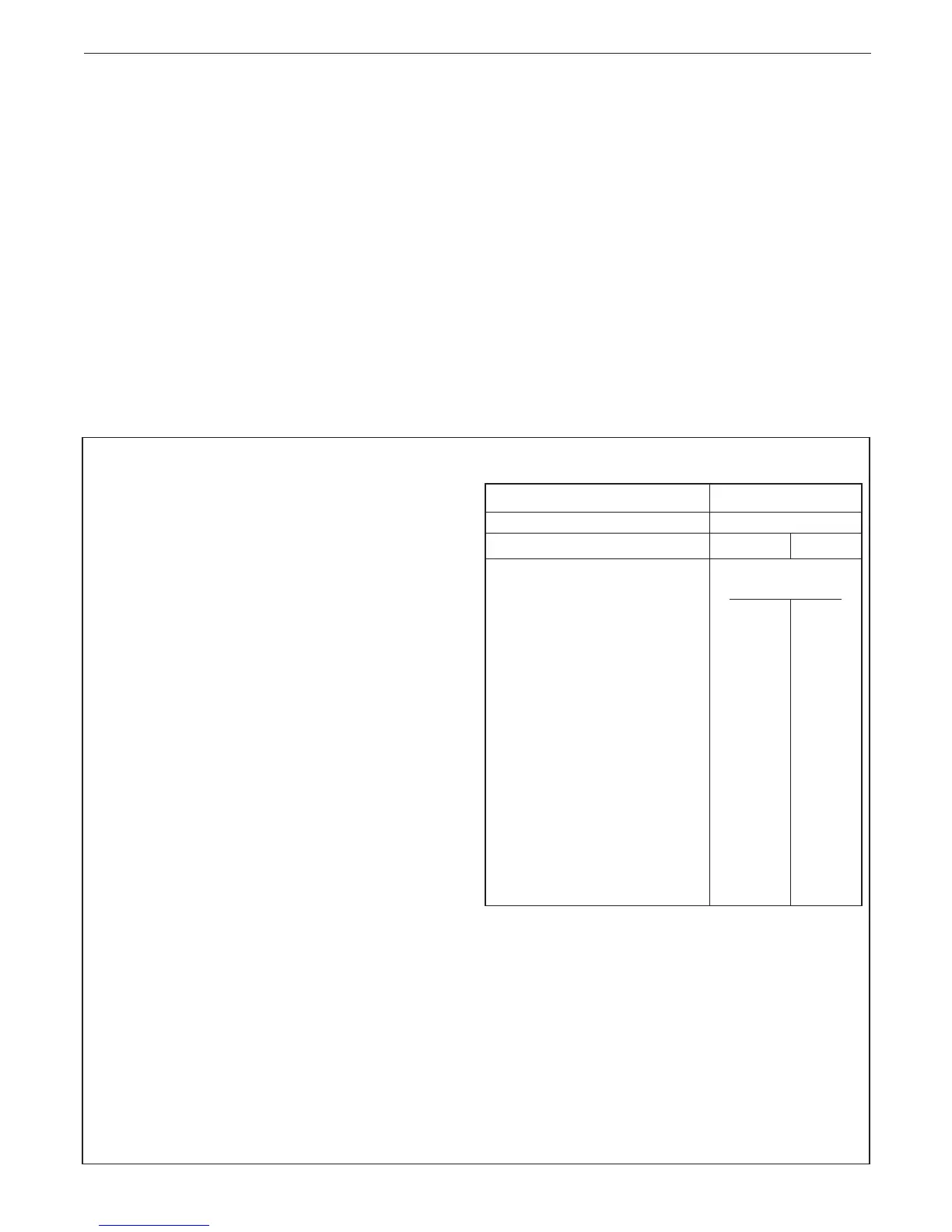
Guidance on vessel sizing is given in Frame 3.
Safety valve setting bar 3.0
Vessel charge pressure bar 0.5 to 0.75
System pre-charge pressure bar None 1.0
System volume Expansion vessel
(litres) volume (litres)
25 1.6 1.8
50 3.1 3.7
75 4.7 5.5
100 6.3 7.4
125 7.8 9.2
150 9.4 11.0
175 10.9 12.9
190 11.9 14.0
200 12.5 14.7
250 15.6 18.4
300 18.8 22.1
For other system volumes
multiply by the factor across 0.063 0.074
 Loading...