35
INSTALLATION
Esprit - Installation and Servicing
maxminmaxmin
preheat on winter boiler on
off summer off
reset
A
J
BC
G
N
T
U
S L R PM
E
F
H
D
K
X
W
esp9265
V
Z
39
INITIAL LIGHTING
1. Check that the system has been filled and that the boiler is
not airlocked. Ensure the automatic air vent caps (W & Z) are
open.
Note.
It is important the burner is not operated before the system is
fully vented of air. If it is necessary to operate the appliance
pump to assist venting of the air this must be done with the
gas service cock turned off.
2. Swing the control box to the working position .
3. Refit the boiler front panel. Refer to Frame 45.
4. Check that all the drain cocks are closed and that the CH
and DHW isolating valves (N, P and R) are OPEN.
5. Check that the electrical supply is OFF.
6. Check that the boiler on/off switch (A) is off, the winter/summer
switch (B) is in the winter position and the preheat switch (C)
is on.
7. Check that the gas service cock (M) is OPEN.
8. Slacken the screw in the inlet pressure test point (L) and
connect a gas pressure gauge via a flexible tube.
9. Switch the electricity supply ON and check all external controls
are calling for heat.
10. CENTRAL HEATING
Set the CH temperature control (D) to maximum and switch
the boiler on/off switch (A) to ON. The boiler control should
now go through its ignition sequence until the burner is
established.
11. If the boiler does not light after 3 attempts the fault code
will be displayed, Press the reset button (H) and the boiler
will repeat its ignition sequence.
When the burner is established the WHITE 'Burner On' light
(F) will be illuminated, the display will show status c.
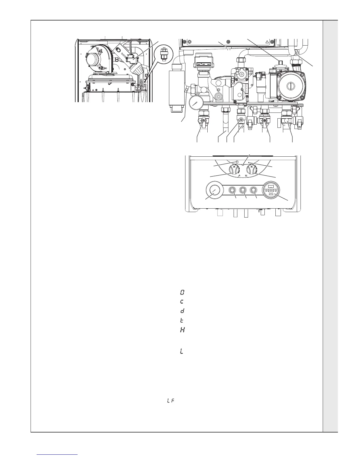
THE DISPLAY
The user control has one light and one display to inform the
user about the status. The display will show the status of the
boiler. The light will show the status of the flame. If no flame is
detected the light is blinking. When the flame is detected the
light will be lit permanently.
Below is a list with display function in normal operation.
Standby, no demand for heat present.
Boiler is active for central heating.
Boiler is active for domestic hot water.
Boiler is heating up the plate heat exchanger.
Boiler is in lockout for a specific error. Display will be
blinking, alternating with a number or letter to show which
error is detected.
Boiler is in lockout for a specific error. Display will be
blinking, alternating with a number or letter to show which
error is detected.
Note.
If the boiler displays fault code ‘LE’ on installation, check the
pressure gauge (J). The required minimum system pressure
cold is 1.0 bar. See Frame 32 if system need filling.
continued . . . .
LEGEND
A. Boiler On/Off switch
B. Winter/Summer Switch
C. Preheat On/Off Switch
D. CH Temperature Control
E. DHW Temperature Control
F. Burner Light
G. Display
H. Reset Button
J. Pressure Gauge
K. Programmer Kit (Optional)
L. Inlet Pressure Test Point
M. Gas Service Cock
N. CH Flow Isolating Valve
P. CH Return Isolating Valve
R. DHW Inlet Isolating Valve
S. DHW Outlet
T. Overheat Thermostat
U. Control thermistor (flow)
V. Return Thermistor
W. Auto Air Vent (Heat exch.)
X. Spark Generator
Z. Auto Air Vent (Pump)
INSTALLATION
 Loading...