47
SERVICING
Esprit - Installation and Servicing
Rear
Front
Combustion
chamber
LH Side
RH Side
esp8866
5
4
6
8
63
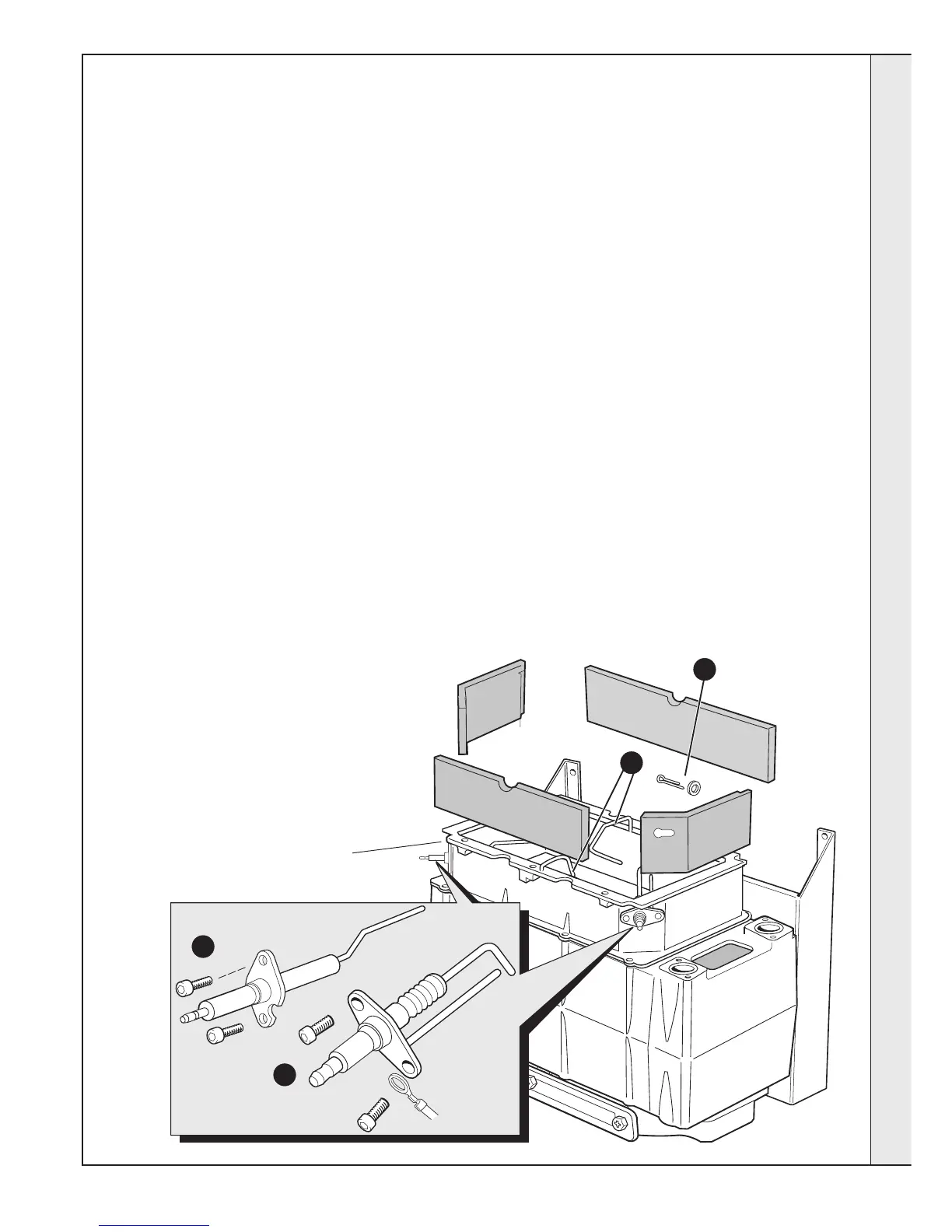
COMBUSTION CHAMBER INSULATION REPLACEMENT
The insulation boards used in the combustion chamber of
this product are made of high temperature glass fibres with
a binder of organic and inorganic materials.
Ideal Stelrad Group recommend that, for your own comfort
and safety and to comply with good working practice, the
procedure described below is followed:
1. Refer to Frame 52.
2. Remove the fan / venturi assembly. Refer to Frame 47.
3. Remove the burner. Refer to Frame 48.
4. Remove the ignition electrode. Refer to Frame 58.
5. Remove the flame detection electrode. Refer to Frame
59.
6. Remove the front and rear ionisation probes. Ionisation
probes are a servicable component and require
inspecting annually. Replace if distorted.
Prior to removal of the board the following protective
equipment should be worn:
z Face mask supplied with the spare part.
z Gloves supplied with the spare part.
7. Damp down the combustion chamber area containing
the insulation boards.
8. Remove the split pin and washer from the RHS of the
combustion chamber.
9. Remove the insulation boards. The replacement boards
are supplied in a plastic bag. This bag should be retained
and the discarded boards should now be placed into it.
10. Sweep any dampened particles and place in the plastic
bag.
11. Fit new insulation boards.
Note.
The boards are designed to be interlocking and should be
fitted as shown.
12. Fit the new split pin and washer in the RHS of the
chamber.
13. Remove the gloves and face mask and place them in the
plastic bag.
14. Wash your hands and any areas of skin which may have
come into contact with any of the particles from the
insulation board.
Note. Seal the plastic bag and dispose of it and its contents
into a commercial tip.
15. Reassemble in reverse order, remembering to re-fit the
ionisation probes first.
16. Check operation of the boiler. Refer to Frame 52.
Fit insulation in the following order:
1. Rear.
2. Left Hand Side.
3. Front.
4. Right Hand Side.
SERVICING
 Loading...