30
INSTALLATION
Esprit - Installation and Servicing
33
ELECTRICAL CONNECTIONS
Wiring should be 3 core PVC insulated cable, not less than
0.75 mm
2
(24 x 0.2mm) and no greater than 1.25mm
2
, and
to BS 6500 Table 16.
Connection must be made in a way that allows complete
isolation of the electrical supply such as a double pole
switch having a 3mm (1/8") contact separation in both
poles, or an unswitched plug and socket, serving only the
boiler and system controls. The means of isolation must
be accessible to the user after installation.
WARNING. This appliance MUST be earthed.
A mains supply of 230 V ~ 50 Hz is required.
The fuse rating should be 3A. All external controls and wiring
must be suitable for mains voltage.
Wiring external to the boiler MUST be in accordance with the
current I.E.E. (BS.7671) Wiring Regulations and any local
regulations.
For IE reference should be made to the current ETCI rules for
electrical installations.
34
ELECTRICAL CONNECTIONS - INSTALLER WIRING
L
N
F1
F2
R1
R2
R3
esp9189
Pre fitted
mains cable
Pre fitted link wire
The Esprit boiler comes pre-fitted with 1m of mains cable.
This must be connected to a permanent live supply and NOT
switched by thermostats/programmers. For installers
wishing to change this cable refer to Frame 35.
The Esprit boiler comes pre-fitted with a link wire between R1
and R2 on the terminal strip. This creates a permanent call
for heat and must be removed when adding a room
thermostat/programmer.
To add thermostat/programmer:
1. Isolate the mains supply to the boiler.
2. Remove the front panel. Refer to Frame 45.
3. Swing the control box down into the servicing position.
Refer to Frame 46.
4. Remove the terminal block cover to access the terminals
for electrical connections.
LEGEND
L Live
N Neutral
F1 Frost Thermostat Switched Live
F2 Frost Thermostat Live Feed
R1 Room Thermostat Switched Live
R2 Room Thermostat Live Feed
R3 Room Thermostat Switched Live
(When using optional internal programmer kits)
esp8854
4
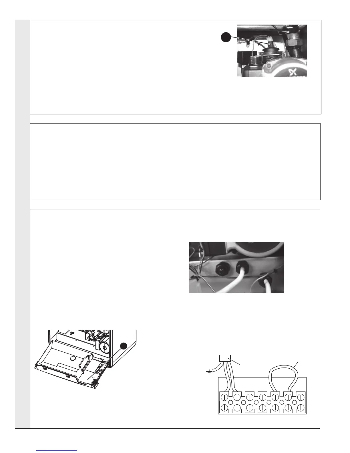
5. Route incoming cables through cable glands provided,
after removing air sealing plugs.
6. Connect wires to terminal block, see instructions
opposite.
7. Re-fit terminal block cover, nibbling out the plastic as
required from the cable entry to secure the cables.
8. Tighten cable gland to provide cable anchorage.
9. Swing the control box back up into the operating condition
and re-fit the front panel ensuring a good seal is made.
32
FILLING
Central Heating
1. Remove the front panel. Refer to
Frame 45.
2. Ensure that the CH isolating
valves are open.
3. Fill and vent the system using the
filling loop, fitted between the DHW
inlet valve and the CH return valve.
Refer to Frame 31 and Frame 4 for
setting pressure.
Check for water soundness.
Note. The domestic hot water flow rate is
automatically regulated to a maximum:
HE24 = 9.6 l/m (2.1 gpm)
HE30 = 12.0 l/m (2.6 gpm)
HE35 = 14.4 l/m (3.2 gpm)
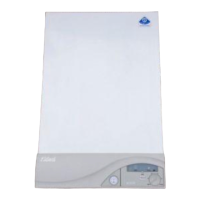
A
IMPORTANT - when filling:
A. Ensure dust cap on auto air vent is
opened up one full turn.
B. When filling, there may be a slight
water leak from the air vent therefore
electrical connections should be
protected.
Domestic Hot Water
1. Fully open all DHW taps and ensure
that water flows freely from them.
2. Close all taps.
INSTALLATION
 Loading...