29
INSTALLATION
Esprit - Installation and Servicing
esp8826
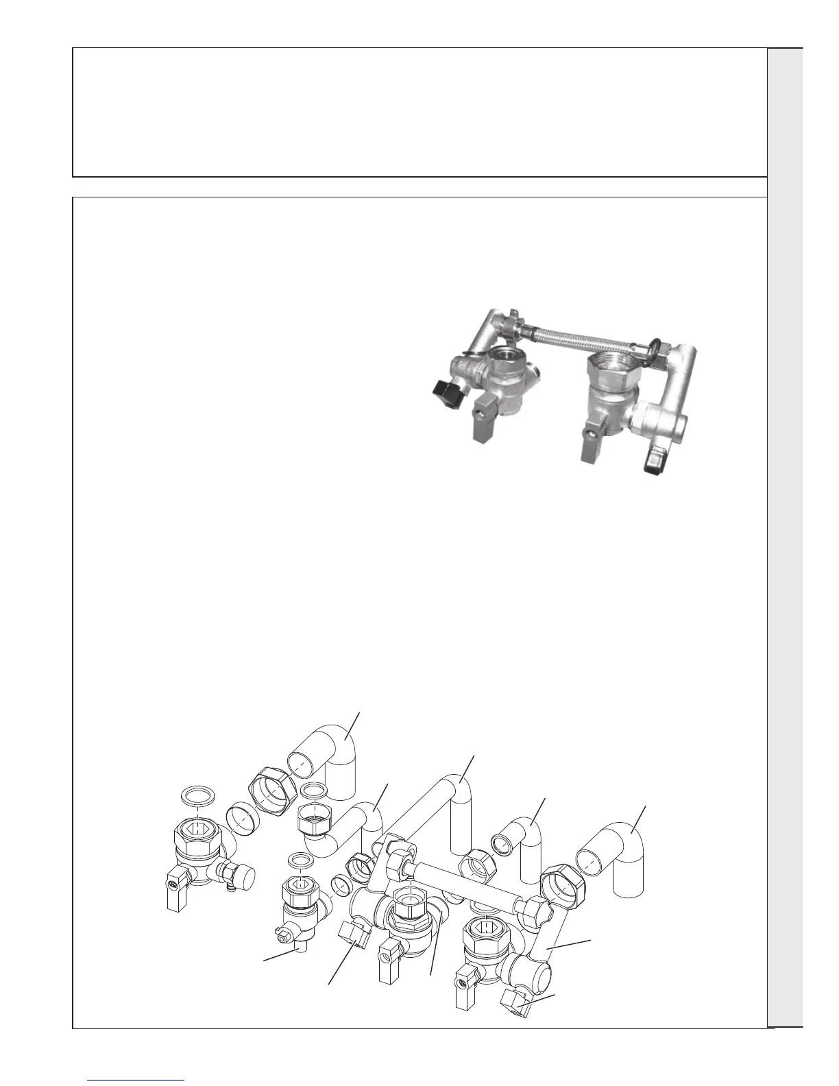
CH Return
Connection
DHW Inlet
Connection
Gas
Connection
DHW Outlet
Connection
CH Flow
Connection
Inlet Pressure
Test Point
Flow
Regulator
Filling Loop Valve
(shown in closed postion)
Filling Loop Valve
(shown in closed postion)
CH Filling
Loop
30
PRESSURE RELIEF VALVE (PRV) OUTLET - (SAFETY VALVE DRAIN)
The PRV outlet is located at the rear RHS of the boiler service connection area.
Connection of additional pipewok to the PRV outlet should be made prior to connection of CH, DHW and gas connections
for ease of access.
The discharge pipe should be positioned so that the discharge of water or steam cannot create a hazard to the occupants
of the premises or damage the electrical components and wiring.
31
WATER AND GAS CONNECTIONS
Included in the hardware pack provided with the boiler are all the necessary isolation valves, seals and pipework to connect
the CH, DHW and gas connections (refer to Frame 9). Components are also provided for an integral filling loop. Each
connection is individually bagged with the correct seals and pipework, and should only be opened when required.
1. Pre-assemble the filling loop between the CH return
and DHW inlet isolation valves as shown in the photo.
2. Attach this assembly to the bottom of the boiler using
the sealing washers provided. The copper tail pipes
may now be connected to the valve outlets.
3. Connect the gas service cock using the washer
provided. The copper tail pipe may now be fitted.
4. Connect the DHW outlet connection
5. Connect the CH flow isolation valve using the washer
provided. The copper tail pipe may now be fitted.
GAS CONNECTION
IMPORTANT. The gas service cock is sealed with a non-
metallic blue fibre washer so must not be overheated when
making capillary connections.
Refer to Frame 2 for details of the position of the gas connection.
N.B. The principle of the 1:1 gas valve ensures that the
Esprit HE range is able to deliver its full output at inlet
pressures down to 14mb. However if dynamic pressures
below 20mb are experienced ensure this is adequate for
ALL other gas appliances in the property.
A boiler gas supply pipe length of 20m and not less than
15mm O.D. can be connected to the boiler via the gas
service cock union.
WATER CONNECTIONS - CH
Notes.
For heating loads in excess of 60,000 Btu/h use 28mm x
22mm connectors to connect the boiler flow and return pipes
to 28mm system pipework.
Do not subject any of the isolating valves to heat as the seals
may be damaged.
WATER CONNECTIONS - DHW
Note. The DHW inlet isolating valve incorporates a flow
regulator and a CH filling loop connection.
INSTALLATION
 Loading...