31
INSTALLATION
Esprit - Installation and Servicing
34
CONT’D ..........ELECTRICAL CONNECTIONS - INSTALLER WIRING
Ideal Boilers offer 4 kits as follows:
(see individual kits for installation instructions)
PROGRAMMER KIT MECHANICAL 24 HOUR- 24 hour mechanical programmer fits into the control box of the boiler. This can be
fitted in conjunction with a room thermostat.
PROGRAMMER KIT ELECTRONIC 7 DAY - 7 day electronic programmer fits into the control box of the boiler. This can be fitted in
conjunction with a room thermostat.
RF THERMOSTAT/PROGRAMMER KIT MECHANICAL 24 HOUR - Combined 24 hour mechanical programmer and room
thermostat with wireless communication to receiver unit which fits into control box of the boiler.
RF THERMOSTAT/PROGRAMMER KIT ELECTRONIC 7 DAY - Combined 7 day programmer and room thermostat with wireless
communication to receiver unit which fits into control box of the boiler.
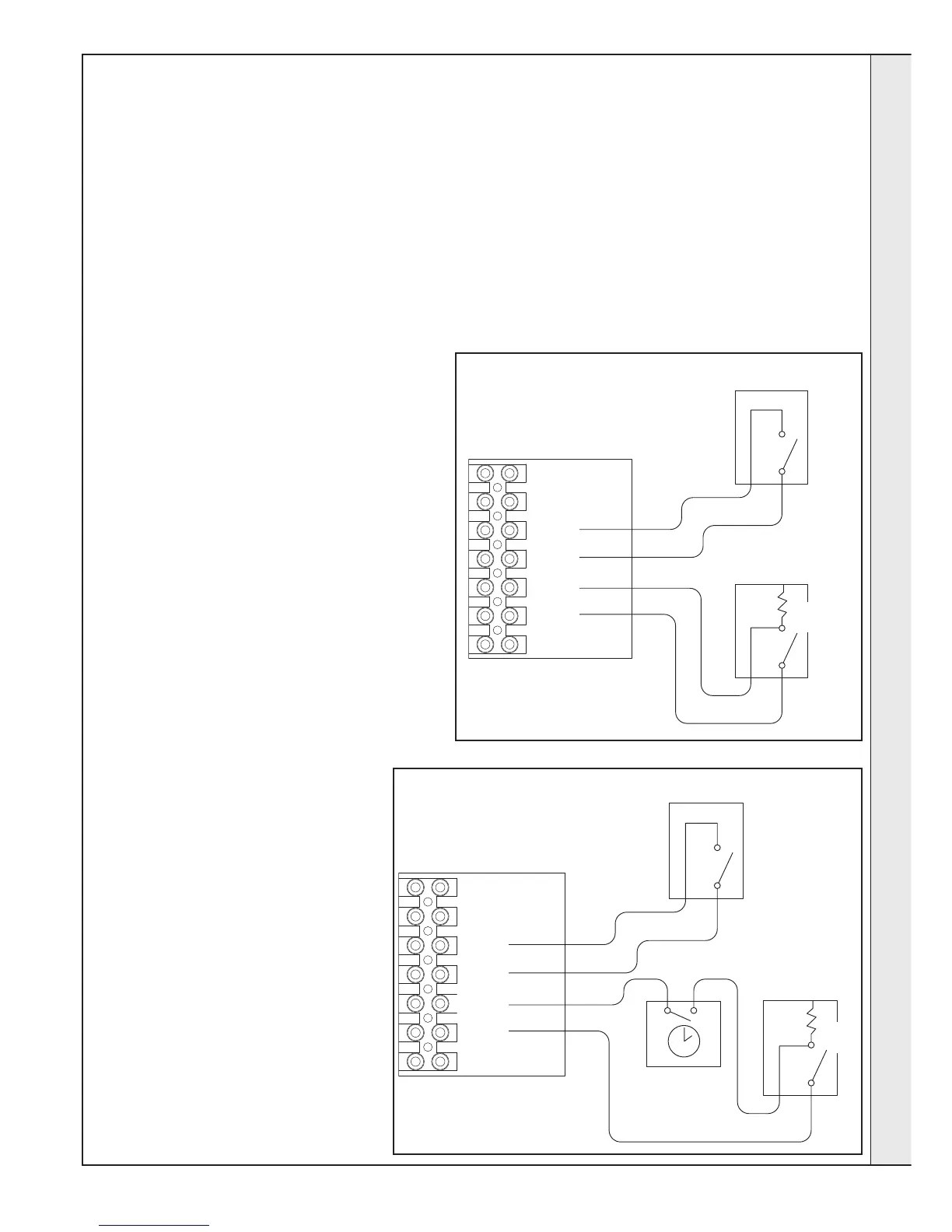
ROOM THERMOSTAT (NO PROGRAMMER)
1. Remove link wire between R1 and R2.
2. Connect room thermostat across terminals R1 and
R2 as shown in diagram A
3. If room thermostat has a neutral connection,
connect this to terminal N (load) in the fused spur.
ROOM THERMOSTAT + PROGRAMMER
1. Remove link wire between R1 & R2.
2. Connect room thermostat and programmer in
series as shown in diagram B.
3. If room thermostat has a neutral connection,
connect this to terminal N (load) in the fused spur.
FROST THERMOSTAT
If parts of the system are vulnerable to freezing or the
programmer is likely to be left off during cold weather, a
frost thermostat should be fitted.
1. Position the frost thermostat in a suitable position,
i.e. area vulnerable to freezing.
2. Connect frost thermostat across terminals
F1 and F2 as shown in diagrams A and B.
esp9396
Optional
Frost Stat
N
R3 connection is used with
integral programmer kit
L
N
F1
F2
R1
R2
R3
Room
Stat
esp9397
Optional
Frost Stat
External
Programmer
L
N
F1
F2
R1
R2
R3
N
Room
Stat
DIAGRAM B - EXTERNAL PROGRAMMER
DIAGRAM A - NO PROGRAMMER
INSTALLATION