17
INSTALLATION
Esprit - Installation and Servicing
4. If the boiler is to be installed with upward piping routed
behind the boiler then the optional stand-off kit should be
used. Care must be taken when cutting the ducts and
marking the wall to suit this condition.
5. Only use water as a lubricant during assembly. Do not use
mineral based oils.
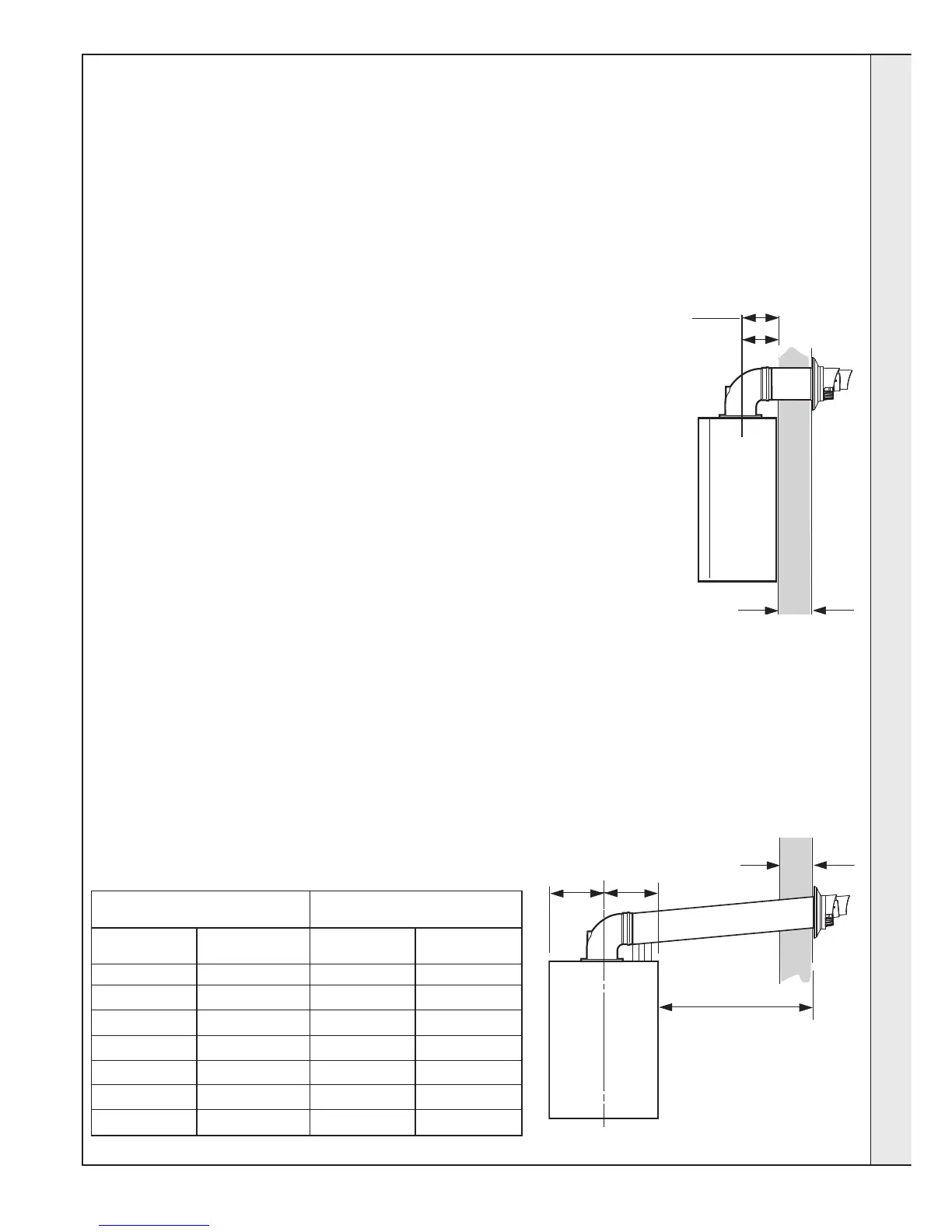
Wall thickness X
169 mm
169 + S = 202mm
esp8815
(with optional
stand-off frame)
FLUE KITS
Pack B - supplied as standard
Pack D - optional extension kit for side flue or
rear flue outlet.
Finishing Kit - Supplied as an optional extra.
Refer to 'Flue Extension Ducts'
IMPORTANT. The boiler MUST be installed in a vertical position
Dimension X - Wall thickness.
Dimension L - Wall thickness plus boiler spacing.
Dimension S - Optional Stand-off frame depth = 33mm
10
DETERMINING THE FLUE LENGTH AND FLUE PACKS REQUIRED
Notes.
1. It is recommended that a support bracket is fitted for every
1 meter of extension pipe used and a bracket should be
used at every joint, to ensure pipes are held at the correct
angle.
If a slip joint coupling is to be used then a bracket should
be used to secure the collar.
2. When extension ‘D’ packs are used the flue duct MUST be
inclined at 1.5 degrees to the horizontal to allow
condensate to drain back into the boiler and out through
the condensate drain.
3. If the telescopic ‘B’ pack, or horizontal flue terminal (600
long) only are used, they may be mounted horizontally.
The 1.5 degrees is taken care of by the inclination of the
flue within the air pipe.
Note. MAXIMUM FLUE LENGTHS:
HE24 & 30 - 6M (HORIZONTAL FLUE)
HE35 - 3M (HORIZONTAL FLUE)
HE24, 30 & 35 - 7.5M (ROOF FLUE)
HE 24, 30 & 35 - 5M PRIMARY AND 17M SECONDARY IS A
TYPICAL MAX. FLUE LENGTH. (For alternative details refer to
Powered Vertical Instructions)
90
O
ELBOW KIT 60/100 (EQUIVALENT FLUE LENGTH RESISTANCE = 1M)
45
O
ELBOW KIT 60/100 (EQUIVALENT FLUE LENGTH RESISTANCE = 0.6M)
HE24, HE30 & HE35 - 18M TOTAL (AIR PLUS FLUE DUCT-60/60 TWIN FLUE KIT)
HE24, HE30 & HE35 - 60M TOTAL (AIR PLUS FLUE DUCT - 80/80 TWIN FLUE KIT)
NOTE. If the option of a loft terminal grille is used with the 80/80 twin flue, then a minimum
of 300mm radial clearance around the grill must be maintained at ALL times.
MINIMUM HORIZONTAL FLUE LENGTHS - TELESCOPIC TERMINAL = 370MM
(Centre Line of turret to outside of wall terminal) - ONE PIECE TERMINAL = 285MM
Total Flue length dimension Flue
(measuring from CL of turret to outside wall)
Rear flue Side flue Extra packs Boiler
dim. X+169 dim. L+225 required Size
Up to 595 mm Up to 595 mm none HE24,30 & 35
Up to 1545 mm Up to 1545 mm Pack D - 1 off HE24,30 & 35
Up to 2495 mm Up to 2495 mm Pack D - 2 off HE24,30 & 35
Up to 3445 mm Up to 3445 mm Pack D - 3 off HE24, 30 & 35*
Up to 4395 mm Up to 4395 mm Pack D - 4 off HE24 & 30
Up to 5345 mm Up to 5345 mm Pack D - 5 off HE24 & 30
Up to 6000 mm Up to 6000 mm Pack D - 6 off HE24 & 30
*Esprit HE35 is capable of 3m flue only
225mm
225mm
Wall thickness X
Side flue length L
SIDE FLUE
REAR FLUE
INSTALLATION
 Loading...