hipot.com 32
Using the Remote I/O
Two 9-pin “D” type connectors are mounted on the rear panel that provides REMOTE-INPUT-OUTPUT control and information.
• These connectors mate with standard 9 pin D-sub-miniature connector provided by the user.
• The output mates to a male (plug) connector while the input mates to a female (receptacle) connector.
• For best performance, a shielded cable should be used. To avoid ground loops, the shield should not be grounded at both
ends of the cable.
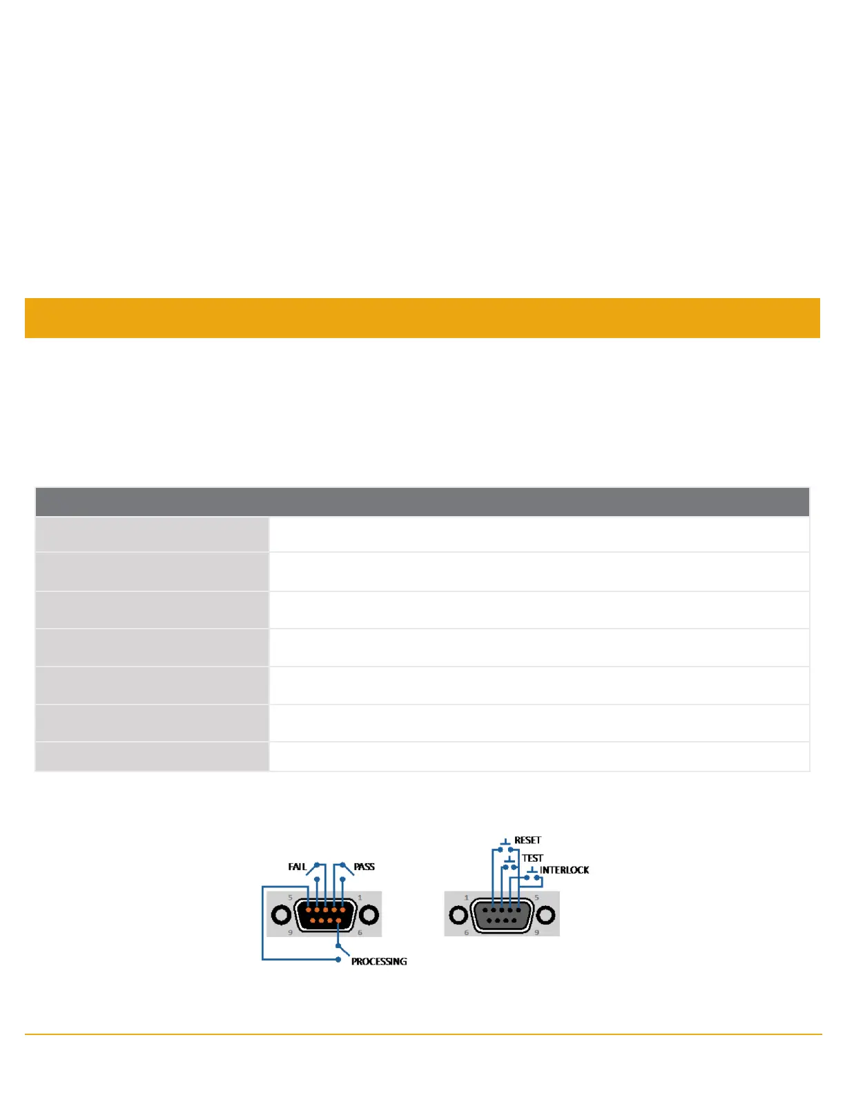
REMOTE I/O Pinouts
Suggested AMP part numbers for interconnecting to the Remote I/O
Part Number Description
205204-4 Plug Shell with Ground Indents
205203-3 Receptacle Shell
745254-7 Crimp Snap-In Pin Contact (for Plug)
745253-7 Crimp Snap-In Socket Contact (for Receptacle)
745171-1 Shielded Cable Clamp (for either Plug or Receptacle)
747784-3 Jackscrew Set (2)
Reviewing Test Results for Multi-step Sequences
After the test is performed, the test results will be indicated on the front panel display.
Pass: If the DUT passes the test, you will hear a short audible beep and the display will indicate the test result.
Fail: If a failure occurs, you will hear a long audible alarm and the red ashing indicator will light up. To stop the alarm, press the
RESET button.
The test results from the memories that are executed can be reviewing by turning the rotary knob left or right. Successive
rotation of the knob will continue advancing to the next result. The results of the last step in the process will be followed by the
rst step when scrolling through the results. Results can be reviewed at any time before the next test is executed. All results are
cleared at the start of the next test cycle.
SIGNAL OUTPUT SIGNAL INPUT
 Loading...