hipot.com 8
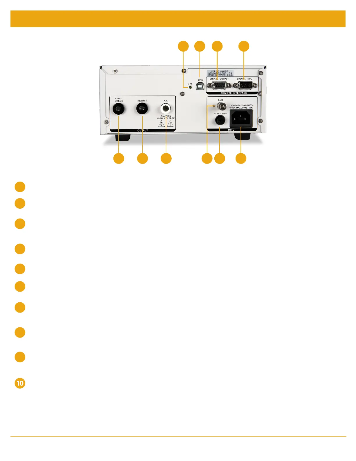
Rear Panel Controls
CALIBRATION ENABLE KEY - To enter the calibration mode press this key while the tester is being powered ON.
USB CONNECTOR - Optional USB port for serial communication. Refer to Option 03 in the Options section.
SIGNAL OUTPUT - 9 pin D subminiature female connector for monitoring PASS, FAIL, and PROCESSING output
relay signals.
SIGNAL INPUT - 9 pin D subminiature male connector for remote control of test, reset, and interlock functions as well as
remote memory tests selection.
OPTIONAL CONTINUITY CHECK PORT - Provides the connection for checking ground continuity.
OPTIONAL RETURN PORT - Provides the return connection for the leakage current.
OPTIONAL HIGH VOLTAGE OUTPUT PORT - Use this jack for the connection of the detachable high voltage test
lead or the adapter box high voltage connector.
CHASSIS GROUND EARTH TERMINAL - This safety ground terminal should be connected to a good earth ground
before operation.
FUSE RECEPTACLE - To change the fuse unplug the power (mains) cord and turn the fuse cap counter clockwise to
remove the fuse.
INPUT POWER RECEPTACLE - Standard IEC 320 connector for connection to a standard NEMA style line power
(mains) cord.
7 8
1
5 6 9 10
2 3 4
1
6
7
8
2
3
4
5
9
 Loading...