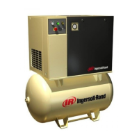
http://air.ingersollrand.com 17
OPERATION AND MAINTENANCE MANUAL GENERAL INFORMATION
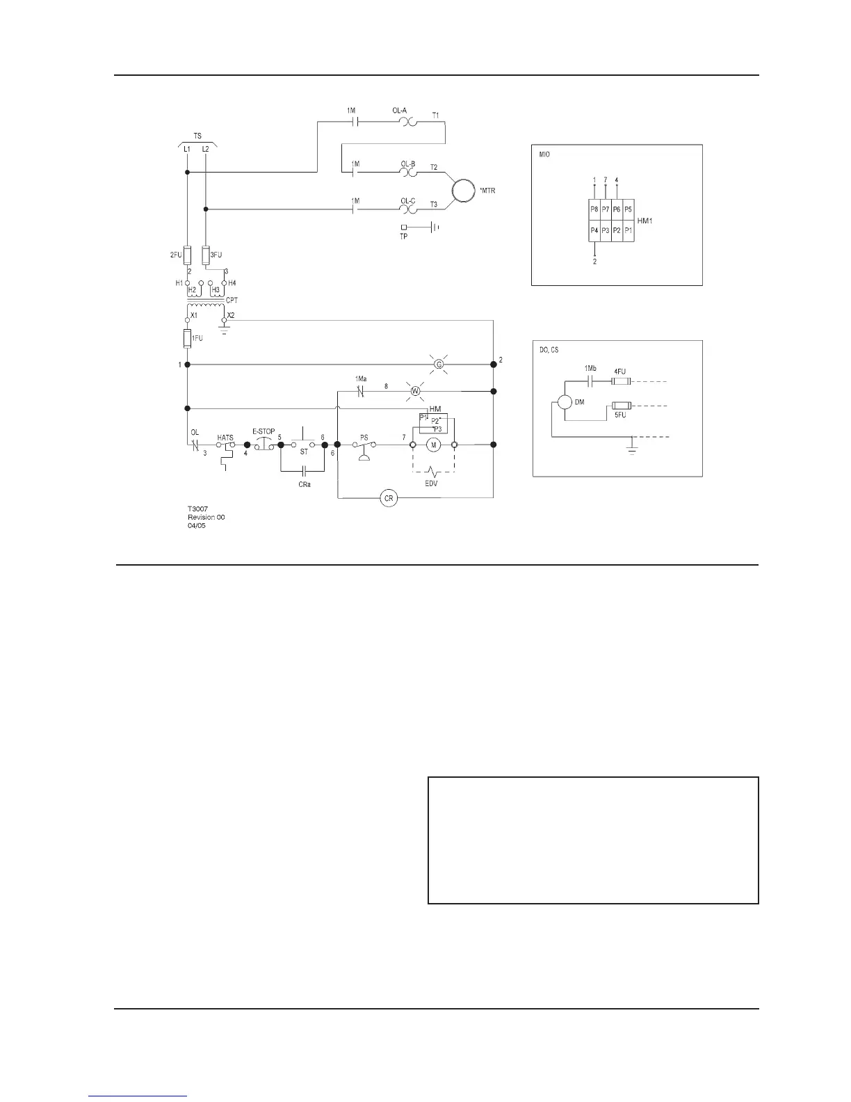
SCHEMATIC, ELECTRICAL UP6 5–15HP FV 1PH 60Hz - U.S.A.
KEY
1FU,
2FU, 3FU
Fuse control circuit M Coil motor starter
4FU, 5FU Fuse, dryer MIO Indicator, maintenance option
1Ma Contact, auxiliary starter (Instead of standard hourmeter)
1Mb Contact, auxiliary starter MTR Motor,compressor
CPT Transformer, control 120/1/50–60 see OL Overload, motor starter
Transformer nameplate for wiring PS Switch, pressure
Connection requirements ST Push button, start
CR Relay, control TP Terminal points
CRa Contact, control relay TS To supply
CS Customer supplied 115v / 1 / 60hz W Standby light
DM Motor, dryer
NOTES
DO Dryer option 1. (*) Furnished, mounted and wired outside of control
panel, if required by order.
EDV Valve, electric drain 2. Circuit shown in normal position de–energized.
E-STOP Switch, emergency stop 3. All wiring to be marked in accordance with this
schematic.
G Power on light 4. All wiring to be in accordance with NEC.
HM Hourmeter
HM1 Indicator, maintenance
 Loading...