http://air.ingersollrand.com 21
OPERATION AND MAINTENANCE MANUAL INSTALLATION / HANDLING
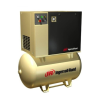
KEY
A Package pre-ller M Motor
B Hole, incoming power supply conduit N Integrated dryer (Optional)
C Gauge, pressure O Compressor and cooling air intake
D Yellow stand–by light P Filter, coolant
E Green power–on light Q Cartridge, coolant separator
F Green start push button R Valve, airend relief
G Emergency stop button S Plug, coolant ller
H Hourmeter T Sight–glass
I Starter box U Plug, coolant drain
J Lifting points V Valve, pilot
K Mounting holes (4 x 14.0mm [0.550”] diameter) W Switch, pressure
L Filter, air inlet X Cooling air exhaust
NOTES
1. Foundation or oor must be level and support all
mounting bolt locations equally. If necessary, shim
or grout the fourth bolt location.
2. Foundation bolts should protect thru nuts a
minimum of 13mm (0.50”) to allow for levelling.
3. Allow a minimum clearance of 1100mm (42”) on
the front and 920mm (36”) on the top, left right
and rear of the package for proper air circulation
and serviceability.
4. Approximate package weight: 298kg (655lbs).
5. External piping shall not exert any unresolved
moments or forces on the unit. Use pipe size as
large or larger at discharge connection.
6. There should be no plastic or pvc piping attached
to this unit or used for any lines downstream.
7. Do not pipe into a common header with a
reciprocating compressor, unless the reciprocating
compressor utilizes a discharge pulsation damper.
8. Sizing of electrical components not supplied
by Ingersoll Rand is the responsibility of the
customer and should be done in accordance with
the information on the compressor data plate and
national and local electrical codes.
NOTE
All dimensions are in millimetres (inches) unless
otherwise stated.
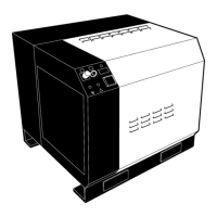
Ensure that the correct fork lift truck slots or marked
lifting points are used whenever the machine is lifted or
transported.
UNPACKING
The compressor will normally be delivered with a
polythene cover. If a knife has to be used to remove
this cover ensure that the exterior paintwork of the
compressor is not damaged.
Ensure that all transport and packing materials are
discarded in a manner prescribed by local codes.
 Loading...