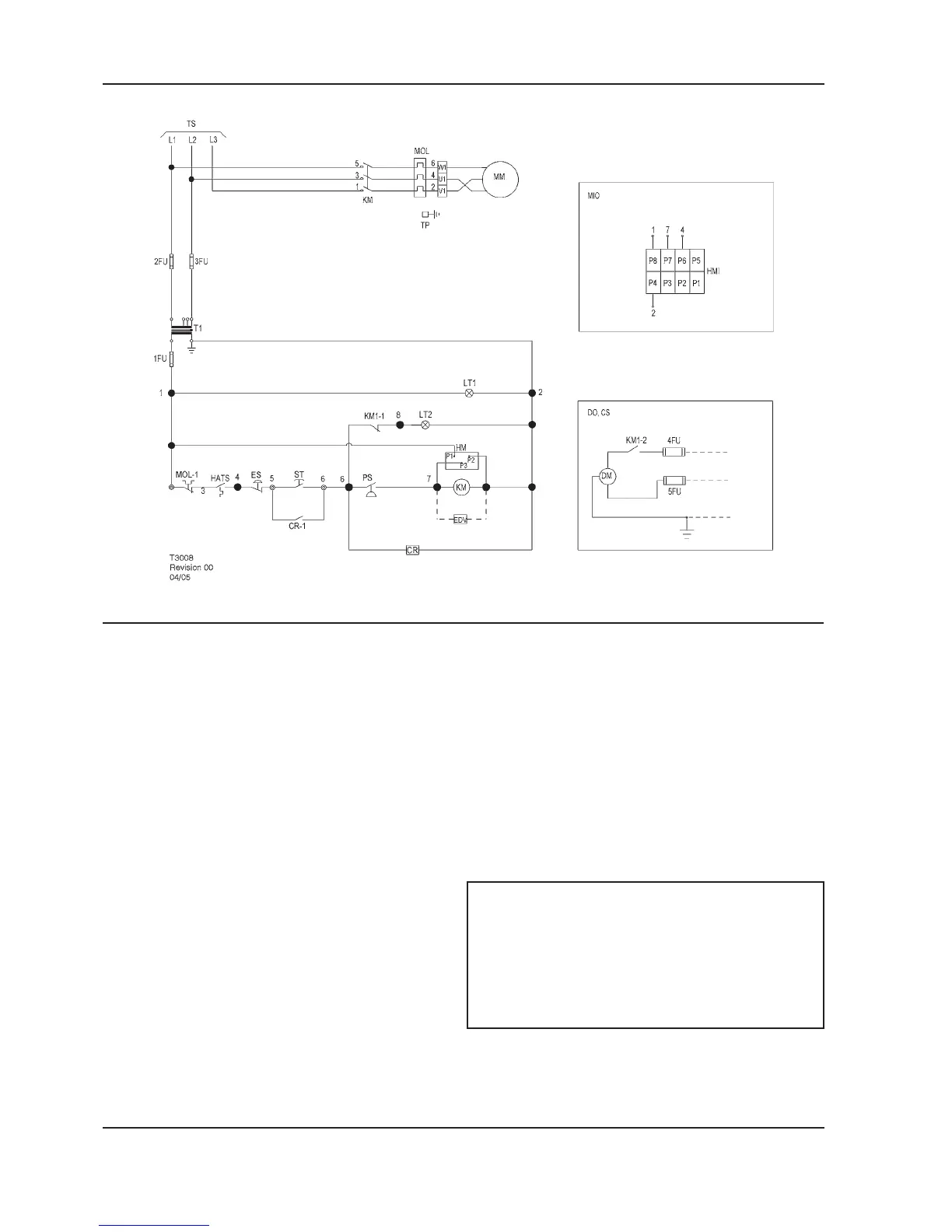
SCHEMATIC, ELECTRICAL UP5 5–15HP FV 3PH 50Hz DOL
KEY
1FU Fuse, secondary MIO Indicator, maintenance option
(Instead of standard hourmeter)
2FU, 3FU Fuse, primary MM Motor, compressor
4FU, 5FU Fuse, dryer MOL Overload, main motor
CR Relay, control MOL-1 Contact, main motor overload
CS Customer supplied 230v / 1 / 50hz PS Switch, pressure
DM Motor, dryer ST Push button, start
DO Dryer option T1 Transformer, control
EDV Valve, electric drain TP Terminal points
ES Switch, emergency stop TS To supply
HATS Switch, high air temperature
HM Hourmeter
HM1 Indicator, maintenance
NOTES
KM Contactor, main 1. (*) Furnished, mounted and wired outside of
control panel, if required by order.
KM–1,2 Contacts, auxiliary. Main contactor 2. Circuit shown in normal position de–energized.
LT1 Light, power on indicator (green) 3. All wiring to be marked in accordance with this
schematic.
LT2 Light, auto restart indicator (white) 4. All wiring to be in accordance with NEC.
 Loading...