http://air.ingersollrand.com 35
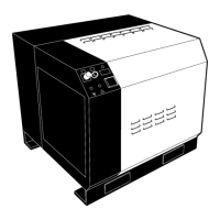
OPERATION AND MAINTENANCE MANUAL INSTALLATION / HANDLING
If there are any deviations from the above, or special
regulations apply, the installation must be planned by a
competent, qualied engineer.
NOTE
All data applies to standard product only.
ELECTRICAL DATA
An independent electrical isolator or disconnect should
be installed adjacent to the compressor.
Feeder cables/wires should be sized by the customer/
electrical contractor to ensure that the circuit is
balanced and not overloaded by other electrical
equipment. The length of wiring from a suitable
electrical feed point is critical as voltage drops may
impair the performance of the compressor.
Feeder cables / wires connections to isolator or
disconnect should be tight and clean.
The applied voltage must be compatible with the motor
and compressor data plate ratings.
The control circuit transformer has dierent voltage
tappings. Ensure that these are set for the specic
applied voltage prior to starting.
CAUTION
Never test the insulation resistance of any part
of the machines electrical circuits, including the
motor without completely disconnecting the
electronic controller (where tted).
CAUTION
Ensure that the motor rotates in the correct
direction as indicated by direction arrows.
 Loading...