10 User interface
Fire detection and extinguishant system
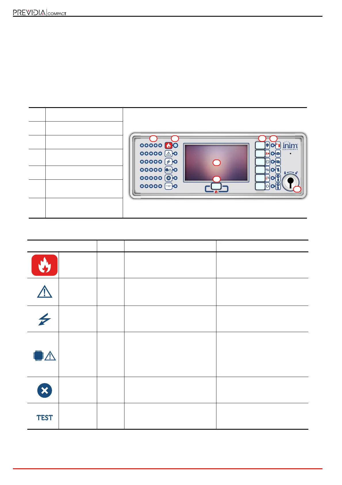
3.2 Function buttons and LEDs
The LEDs on the sides and below the screen provide visual signals which indicate the general status of the system,
whereas the function buttons allow fast execution of all the main operations.
The key permits level 1 (public level) to pass to level 2 (supervisor level). When turned clockwise the key will generate a
pulse which places the control panel in level 2 status. The control panel will return to level 1 if no buttons are pushed
within 20 seconds.
[A]
Touchscreen display
[B]
Status LED
[C]
Function buttons
[D]
LED and multiple-alarm
button
[E]
Access-key slot
[F]
Zone status LEDs
(only on certain models)
[G]
Extinction channel status LED
(only on certain models)
Status LED Colour On solid Flashing
Alarm Red Fire alarm running. Fire alarm memory.
Fault Yellow
A fault (of any type) is present on the
system.
The details of any active faults are
shown on the screen.
Fault memory.
A fault has been solved.
ON Green The system is functioning.
CPU Fault Yellow
The CPU of the control panel is out
of service or one of the
microcontrollers inside the cabinet
does not respond.
If the fault does not clear when the
Reset button is pressed, contact the
technical-assistance service.
CPU fault memory.
The control panel CPU has reset and
restarted.
Disabled Yellow
One or more of the system
elements has been disabled.
Test Yellow
One or more of the system
elements has been put in test mode.
26 27 28 29 30
21 22 23 24 25
16 17 18 19 20
11 12 13 14 15
06 07 08 09 10
01 02 03 04 05
TEST
2
27
16
7
8
9
11 12
4
4
 Loading...