18 Viewing the system
Fire detection and extinguishant system
5.3 Visualization of the system status
The System status button (paragraph 3.3 - [A], accessible at level 1) accesses a section which allows you to view the
status of the various system elements.
The Control panel access button allows you to select one of the Previdia control panels configured in the network to
which the control panel you are accessing belongs. Once the control panel has been selected, the system status screen
and the access buttons [A] will make reference to the selected control panel, indicated by the string below [C]. If the
selected control panel is different from the one in use, the information provided by the alarm counter [B] and by the
Revision button [D] will no longer be available.
A superior access level (2 or 3) allows the user to work on the elements being viewed and carry out operations such as
enable, disable, activation or test. Access to these functions is reserved to persons with supervisor level access who have
been instructed in system management and who have knowledge of the system parts.
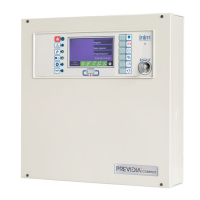
The buttons for viewing purposes [A] give access to the following sections:
[A]
Access buttons to view
the status of the system
elements
[B]
Indicator of the number
of alarms logged by the
control panel in use
[C]
Description of the control
panel being viewed
[D]
Button for displaying the
firmware revision of the
control panel in use
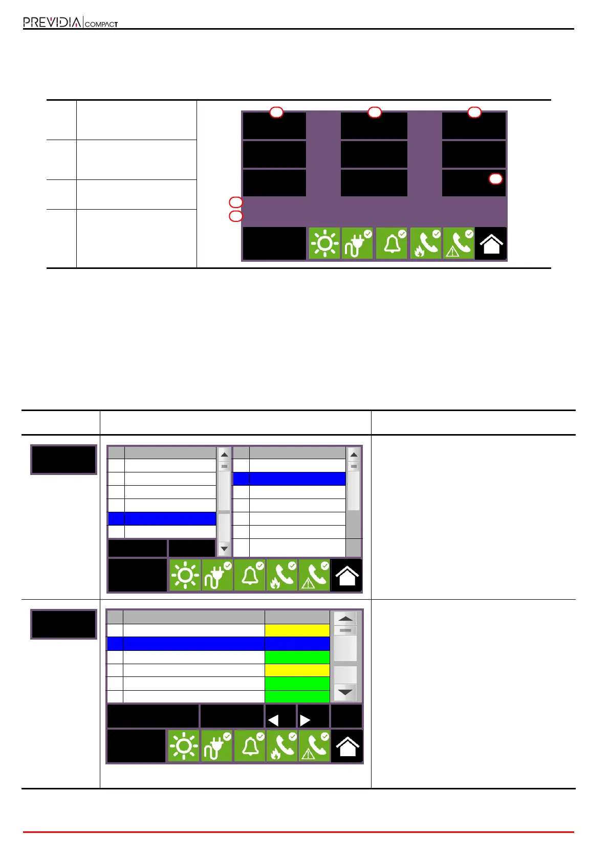
Button Display Section
Section for the selection of the control panel
whose parts you wish to view.
It is possible to select a cluster (group of
control panels connected through a LAN
network) and a single control panel or repeater
from the selected group.
The status of the selected control panel is
displayed after the OK button is pressed.
Section for the viewing of the zones of the
selected control panel.
The section is divided into pages that show a
maximum of 100 zones, navigable by means
of the arrow scroll buttons at the bottom. The
status of each zone is shown and made
distinctive by colour:
• Green, zone in standby
• Yellow, zone in fault status, in test status or
bypassed
• Red, zone in alarm status
• Blue, selected zone
By selecting a zone, it is possible for a user
with access level 2 to put a zone in test status
or to change its bypassed/unbypassed status
(refer to the Disable and Test buttons).
Panel Group I/O Line
Zone Timers Extinction
Point
Dialer
Revisions
Alarm Counter: 23
Previdia Compact control panel
Access level:1
D
A
B
A
C
A
N. Network N. Control panel
0 This cluster 0 This control panel
1
Cluster A 1 Control panel A
2 Cluster B 2 Repeater
4
Cluster C 3 Previdia Compact
5 Cluster D 4 Previdia Max
6 5
Esc OK
6
Access
level:1
N. Zone Status
1 Zone 1 In Test
2 Zone 2 Stand-by
3 Zone 3 Stand-by
4
Zone 4 Fault
5 Zone 5 Stand-by
6
Zone 6 Stand-by
Disable Tes t Esc
Access
level:2
 Loading...