Chapter 3 Mechanical and Electrical Installation
- 34 -
Type Terminal Name Function Description
Digital
outputs
DO1-CME Digital output 1
Optically-coupled isolation, dual-polarity open collector output
Output voltage range: 0 to 24V
Output current range: 0 to 50mA
Note that CME and COM are internally insulated, but are
shorted externally by a jumper. In this case, DO1 is driven
by +24 V by default. Remove the jumper if you need to apply
external power to DO1.
DO1 is connected to the relay extension card (MD28IR1) by
default. That is, the CS200 has changed DO1 into relay output.
FM- COM Digital output 2
When used as an open-collector output, the specication is the
same as DO1.
Relay
outputs
T/A-T/B
Normally-closed (NC)
terminal
Contact driving capacity
250 VAC, 3 A, COSØ = 0.4
30 VDC, 1 A
T/A-T/C
Normally-open (NO)
terminal
Auxiliary
interfaces
J12
Extension card
interface
Interface for the 28-core terminal and optional cards (I/O
extension card, PLC card and various bus cards)
J3 PG card interface Opyional, interface of OC encoder, UVW encoder and resolver
J7
External operation
panle interface
Connect to an external operation panel.
3.2.5 Wiring Diagrams of Input/Output Terminals
■
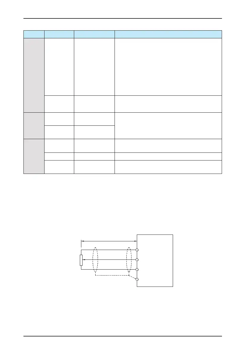
AI Wiring
Analog signals at low levels can suffer from the effects of external interference. To reduce this effect, it is important
to use shielded cables shorter than 20 m long to carry analog signals. As shown in Figure 3-17, in applications
where the analog signals suffer from the effects of severe external interference, install a lter capacitor or a ferrite
magnetic core at the source of the analog signal.
Figure 3-16 Wiring of analog input terminal
+10V
AI1
GND
Potentiometer
PE
< 20 m
CS200
 Loading...


