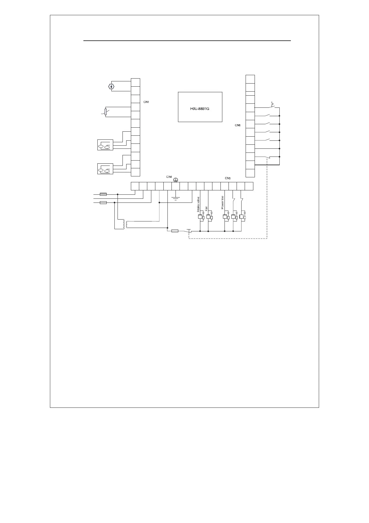
3.6 Arrangement 1: Controlling Signal Wiring Diagram
485A2
485B2
X7
X6
X5
X4
X3
X2
X1
X0
COM
P24
Emergency stop
Air filter clog
Oil filter clog
Separator clog
Fine separator clog
..
CT1A
CT1B
CT1C
CT2A
CT2B
CT2C
P1-
P1+
..
T1+
T1-
..
CT1
CT2
4-20mA
Pressure
transmitter
PT100
C1 Y0 Y1 Y2 Y3 Y4
Y
5
A B C L N PE
T
L1
L2
L3
380V:220V
Emergency
stop
KM3
KM4 KM5
KM4
KM5
KM1
a
b
c
a
b
c
type
Y
type
Fan
Main
motor
FU1
FU2
FU3
Thermal relay contact
Figure 3-4 Controlling signal wiring diagram˖Both main motor and fan
are driven by power-line
Note:
z The main motor adopts the Y-Ƹ startup mode. If power-line direct
startup mode is used, kM4 and kM5 can be omitted.
z The 380V/220V transformer in Figure 3-4 is isolation type
controlling transformer. You can select the model with capacity of
approximate 50VA.
efesotomasyon.com

 Loading...