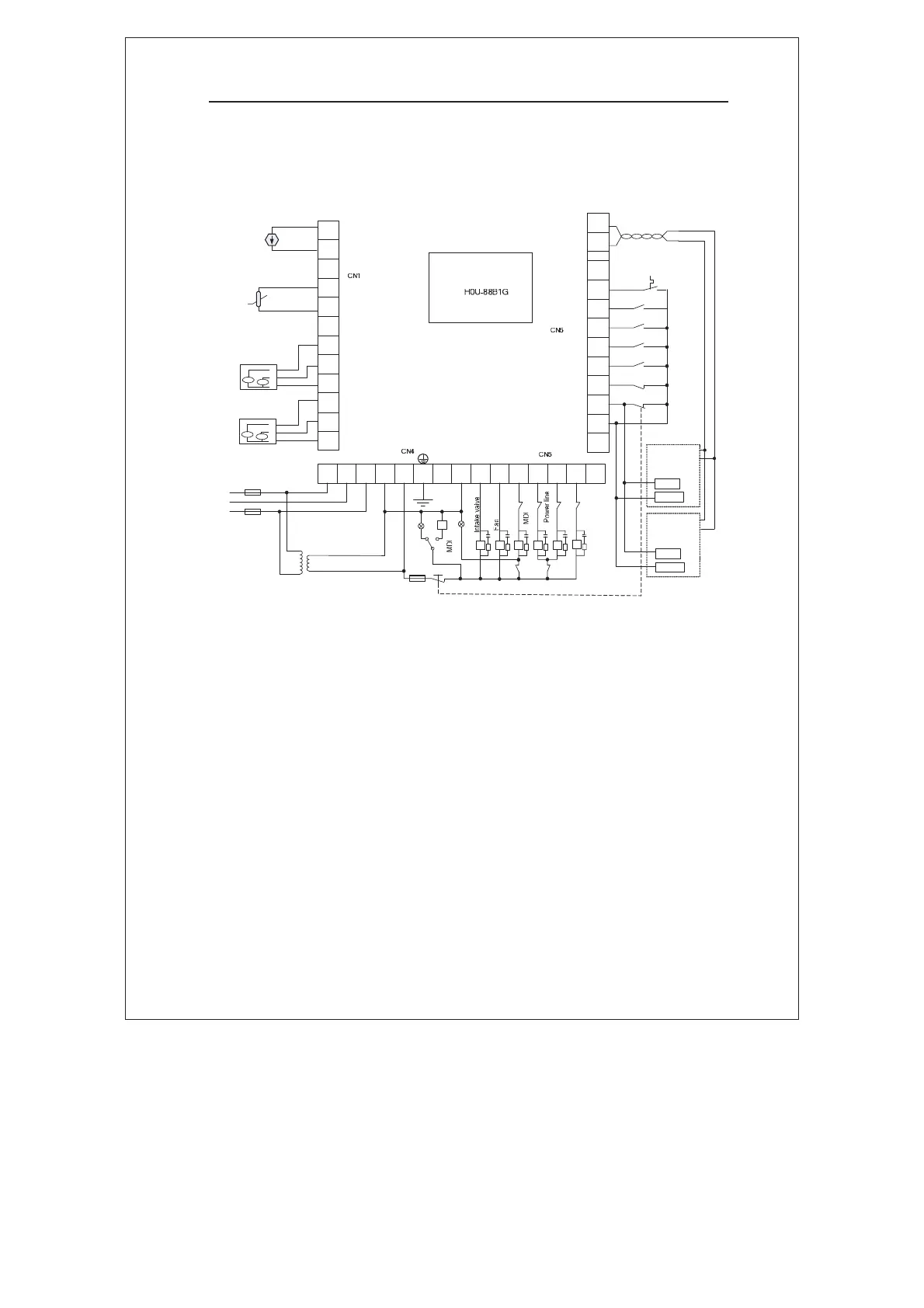
3.14 Arrangement 5: Controlling Signal Wiring Diagram
Both Main Motor and Fan Adopt the MDI/Power-line Compatible Drive
Mode
485A1
485B1
X7
X6
X5
X4
X3
X2
X1
X0
COM
P24
Emergency stop
KA
Air filter clog
Oil filter clog
Separator clog
Fine separator clog
..
CT1A
CT1B
CT1C
CT2A
CT2B
CT2C
P1-
P1+
..
T1+
T1-
..
CT1
CT2
4 20mA
Pressure
transmitter
PT100
C1 Y0 Y1 Y2 Y3 Y4
Y5
A B C L N PE
T
L1
L2
L3
380V:220V
Power
line
GP
BP
KA
KA
KM2
KM3
KM4 KM5
KM3 KM2 KM5
KM4
KM1
SW
KA
a
b
c
a
b
c
Y
typle
type
Fan
Main
motor
COM
DI1
FU1
FU2
FU3
COM
DI1
Thermal relay contact
Main motor
inverter
Fan inverter
Connecting to RS485 port
of MD320 inverter
Emergency stop
485+
485-
485+
485-
Figure 3-12 Controlling signal wiring diagram when both main motor
and fan adopt the MDI/power-line compatible drive mode
Note:
Thermal relay is optional for protection. Signal logic can be set on
the controller. If the motor current is detected by CT, thermal relay is
unnecessary.
efesotomasyon.com

 Loading...