Chapter 3 Mounting and Wiring
3.1 Wiring the Controller
The H0U-88B1G controller is connected with the MD 320 Series
inverter using the RS485 signal twisted cables at the communication
ports (485A1 and 485B1).
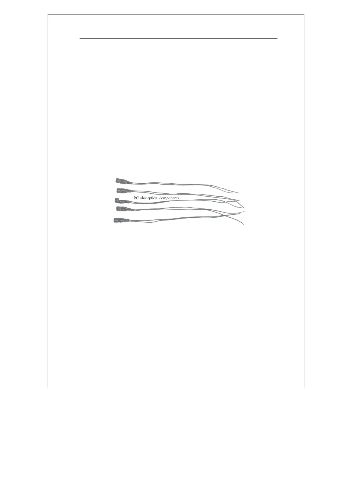
Both contactor coil and solenoid valve are inductive components.
Electric spark will be produced between the contacts upon
switch-on/switch-off operation, which will incur magnetic interference
and influence the service life of the controller output contacts. Thus,
remember to connect RC absorption components to these components
in parallel. For details on connection, see the wiring diagram.
Figure 3-1 RC Absorption Component for Inductive Load
3.2 Drive Modes of Screw compressor
The screw compressor applies to the following drive modes through the
H0U-88B1G controller:
1˅ Main motor: power-line drive (Y-Ƹ startup)
Fan: power-line drive
2˅ Main motor: MDI drive
Fan: power-line drive
3˅ Main motor: MDI drive
Fan: MDI drive
4˅ Main motor: MDI/power-line (Y-Ƹ startup) compatible drive
Fan: power-line drive
5˅ Main motor: inverter/power-line (Y-Ƹ startup) compatible drive
efesotomasyon.com

 Loading...