Version : 1.4
Date of issue : 03-07-14
2.3 Electrical Wiring of NICE 1000
Electrical wiring includes Power terminal, DBR, Main Control Board wirings, Extend board (If
present) and PG card (for Feedback device, Encoder) wirings
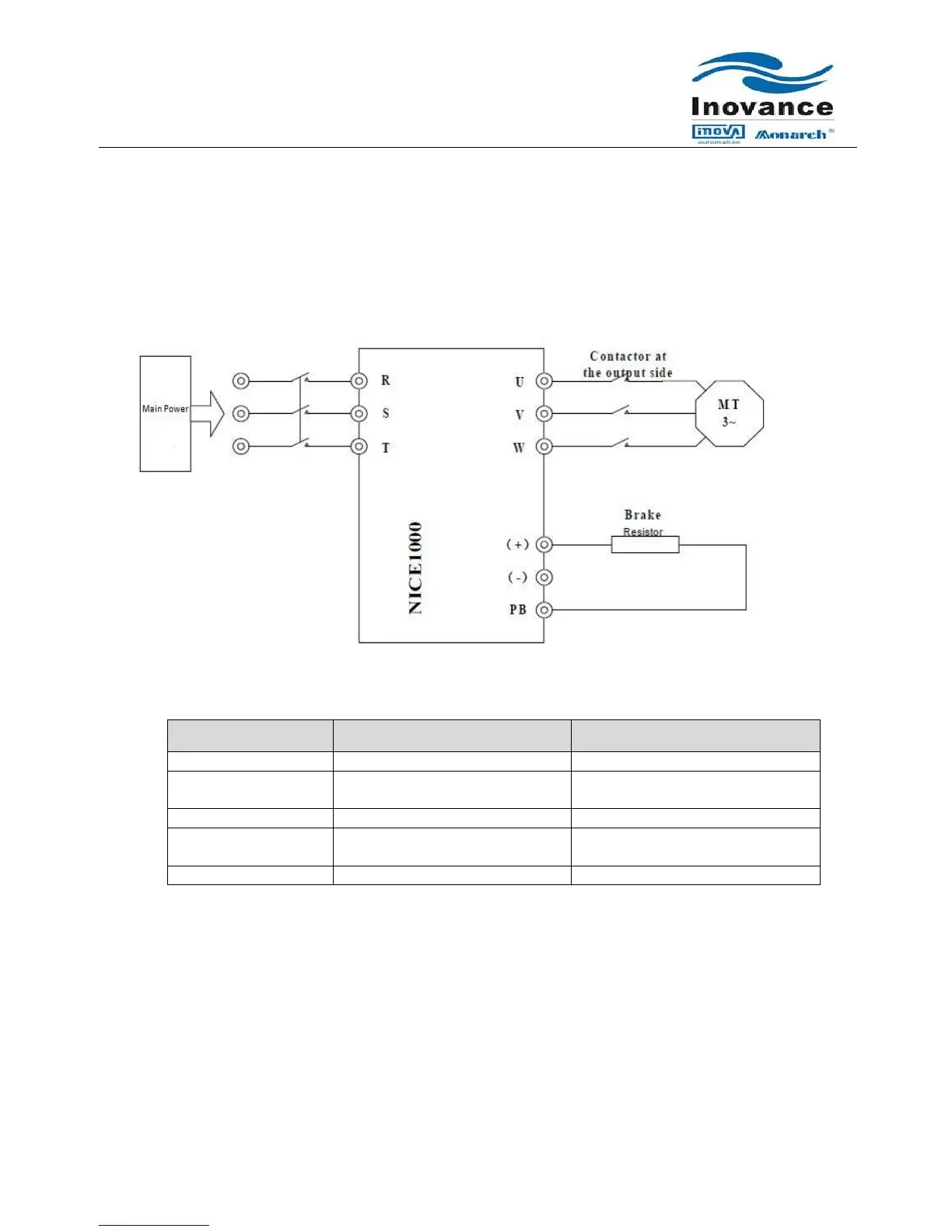
2.3.1 Power Terminal Connection and Terminal Function:
a) Power Circuit:
b) Terminal Function:
3-Phase power input terminal
Positive and Negative terminals of
DC bus
Terminal for brake resistor
To connect External Brake Resistor
Controller Output Power
Terminal
To connect the 3 phase hoist Motor
To be connected with Earth Bus bar
Controller output cables of U, V and W should be routed in separate metal pipe with Grounding and
apart from the Control circuit cables and Encoder cable.
If the cables between the motor and controller are too long, Electrical resonance may occur which make
the NICE controller go into protective status.
Grounding terminal must be connected to proper Earth point; the grounding cable should be thick and
short. The recommended grounding cable should be Yellow-Green cable above 4sq.mm with multi
strand copper cores.
Grounding resistance should be less than 4. Don’t share the earth with neutral line of the main supply.
 Loading...