5.2 Input and Output functional sequence of MCTC-MCB-G of NICE 1000
After switching ON the controller MCBs, the Safety Contactor (SC), Door Lock
Contactor (DLC) and JT relay will get ON if Safety Circuit is properly closed
Once SC contactor ON, the three phase power supply will be given to the Main NICE
drive(Note: If SC is OFF, then there would not be any display on Drive on board
Display)
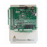
Input terminal points X1~X24 of MCB located left side of the Board are Positive
Logic Signal Inputs which needs +24VDC positive power supply for enabling and
disabling the any given input signal
High Voltage Input terminal Points (X25~X27) of MCB which located bottom side of
the Board are Active High Inputs which needs Phase (P) of 110VAC power supply for
enabling and disabling the safety circuit function.
The 110VAC voltage safety points (X25~X27) are very significant and most priority
inputs in the NICE1000 Lift controller
Err41 will be displayed if the Safety circuit feedback LED X25 is OFF. The safety
circuit wiring should be followed as per the NICE1000 Electrical drawing.
Err35 will be displayed on every power ON until the Learn Run/Shaft Tuning is done.
Err35 will not affect the Inspection Run
For PMSM Gearless machine, Err20 will be displayed if Machine Encoder is not
connected with suitable PG-E card on NICE unit, Encoder Parameter is not set properly
(F1-00=0) and also if the encoder signal wiring sequence is wrong/improper
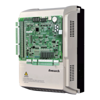
If all the power supply connections and field wirings are ok, then the corresponding
Green LED’s on the Main Control Board (Located above the Drive) will glow.
5.3 Software version verification
Parameter FA-04 is for software version
 Loading...