Desktop Board Features
13
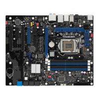
Table 2. Intel Desktop Board DP55KG Components
Label Description
A PCI bus connector
B PCI Express 2.0 x4 connector (x4 electrical; x16 compatible)
C PCI bus connector
D PCI Express 2.0 x8 connector (x8 electrical; x16 compatible)
E Front panel audio header
F S/PDIF header
G PCI Express 2.0 x1 connector
H Rear chassis fan header
I PCI Express 2.0 x1 connector
J PCI Express 2.0 x16 connector (x8/x16 electrical)
K Battery
L Back panel connectors
M Vertical USB connector
N 12 V processor core voltage connector (2 x 4 pin)
O Processor fan header
P Processor LED
Q Voltage regulator LED
R Processor socket
S POST code LED display
T DDR3 Channel A, DIMM 0 and DIMM 1 sockets
U DDR3 Channel B, DIMM 0 and DIMM 1 sockets
V Onboard power button
W Standby power indicator LED
X Main power connector (2 x 12 pin)
Y SATA drive activity LED
Z Front panel header
AA Back panel CIR transmitter (output) header
BB Front panel CIR receiver (input) header
CC Alternate front panel power LED header
DD Front chassis fan header
EE USB 2.0 headers
FF IEEE 1394a header
GG BIOS configuration jumper block
HH Serial ATA connectors
II Chassis intrusion header
JJ BlueTooth* module
KK Speaker
LL Auxiliary PCI Express graphics power connector (SATA-style)
MM Auxiliary chassis fan header
 Loading...