Intel Desktop Board DP55KG Product Guide
54
IEEE 1394a Header
Figure 27, H shows the location of the IEEE 1394a header. Table 11 shows the pin
assignments and signal names for the IEEE 1394a header.
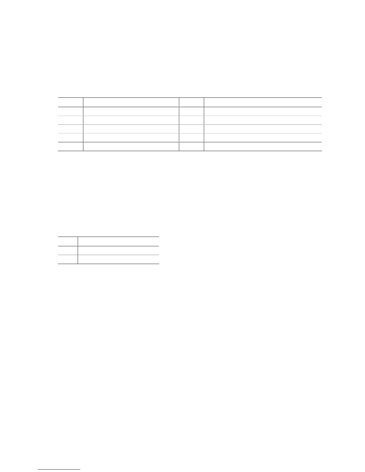
Table 11. IEEE 1394a Header Signal Names
Pin Signal Name Pin Signal Name
1 TPA1+ 2 TPA1-
3 Ground 4 Ground
5 TPA2+ 6 TPA2-
7 +12 V 8 +12 V
9 Key (no pin) 10 Ground
Chassis Intrusion Header
Figure 27, I shows the location of the chassis intrusion header. This header can be
connected to a mechanical switch on the chassis to detect if the chassis cover is
removed. This switch should be in the open position when the chassis cover is
installed and closed when the cover is removed.
Table 12 shows the pin assignments and
signal names for the chassis intrusion header.
Table 12. Chassis Intrusion Header Signal Names
Pin Description
1 Intruder#
2 Ground
 Loading...