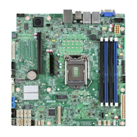
Intel® Server Board S1200SP Family Technical Product Specification
21
3. Processor microcode
4. Memory Mapped I/O (MMIO)
5. Manageability Engine (ME)
6. BIOS flash
3.3.2 Memory RAS Features
For Intel
®
Server Board S1200SP product family, the form of Memory RAS provided is Error Correction Code
(ECC). ECC uses extra bits – 64-bit data in a 72-bit DRAM array – to add an 8-bit calculated Hamming Code to
each 64 bits of data. This additional encoding enables the memory controller to detect and report single or
double bit errors, and to correct single-bit errors.
There is a specific step in memory initialization in which all of memory is cleared to zeroes before the ECC
function is enabled, in order to bring the ECC codes into agreement with memory contents.
During operation, in the process of every fetch from memory, the data and ECC bits are examined for each 64-
bit data plus 8-bit ECC group. If the ECC computation indicates that a single bit Correctable Error has occurred,
it is corrected and the corrected data is passed on to the processor. If a double-bit Uncorrectable Error is
detected, it cannot be corrected. In each case, a Correctable or Uncorrectable ECC Error event is generated.
For Correctable Errors, there is a certain tolerance observed, since a Correctable Error can be generated by
something as random as a stray Cosmic Ray impacting the DIMM. Correctable Errors are counted on a per-
DIMM basis, but are just silently recorded until the tolerance threshold is crossed. The Correctable Error
Threshold for Intel
®
Server Board S1200SP product family board is set at 10 events. When the 10
th
CE occurs,
a single Correctable Error event is logged.
3.3.3 Post Error Codes
The range {0xE0 - 0xEF} of POST codes is used for memory errors in early POST. In late POST, this same range
of POST code values is used for reporting other system errors.
• 0xE8 – No Usable Memory Error: If no usable memory is available, the BIOS emits a beep code and
displays POST Diagnostic LED code 0xE8 and halts the system.
• This can also occur if all memory in the system fails and/or has become disabled during memory
initialization. For example, if a DDR4 DIMM has no SPD information, the BIOS treats the DIMM slot as if no
DDR4 DIMM is present on it. Therefore, if this is the only DDR4 DIMM installed in the system, there is no
usable memory, and the BIOS goes to a memory error code 0xE8 as described above.
• 0x53/0x55/0XE8: DIMM SPD does not respond or DIMM SPD Read Error, the DIMM will not be detected,
if the SPD does not respond, which could result in No memory Installed or No Usable Memory Error Halt
0X53, 0x55, or 0xE8, or could result later in an invalid configuration if the no SPD DIMM is in Slot 1 on the
channel.
• 0x51 – Memory SPD Error: If the DIMM does respond but the SPD cannot be successfully read, that would
cause a Memory SPD Error, memory error halt 0X51. For each memory channel, once the DIMM SPD
parameters have been read, they are checked to verify that the DIMMs on the channel are a valid
configuration, DIMM speed and size, ECC capability, and in which memory slot the DIMMs are installed. An
invalid configuration will cause the system to halt.
• 0xEA – Channel Training Error: If the memory initialization process is unable to properly perform the

 Loading...