Intel® Server Board S1200SP Family Technical Product Specification
75
• Hard Drive Activity LEDs
• System Status LED
• System ID LED
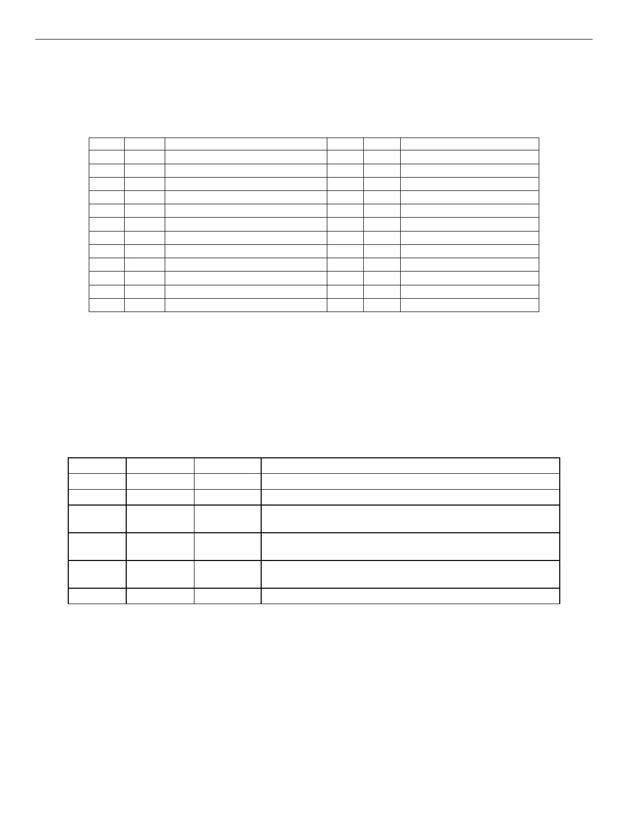
The following table provides the pin-out for this connector:
Table 33. Front Panel 24-pin Connector Pin-out (J9E1)
3.3V (HDD Activity LED Anode)
Pull-up (1-wire Temp Sensor)
8.4.1 Power/Sleep Button and LED Support
Pressing the Power button will toggle the system power on and off. This button also functions as a sleep button
if enabled by an ACPI compliant operating system. Pressing this button will send a signal to the integrated
BMC, which will power on or power off the system. The power LED is a single color and is capable of supporting
different indicator states as defined in the following table.
Table 34. Power/Sleep LED Functional States
System power is off, and the BIOS has not initialized the chipset.
Mechanical is off, and the operating system has not saved any
context to the hard disk.
Mechanical is off. The operating system has saved context to the
hard disk.
DC power is still on. The operating system has saved context and
gone into a level of low-power state.
System and the operating system are up and running.
8.4.2 System ID Button and LED Support
Pressing the System ID Button will toggle both the ID LED on the front panel and the Blue ID LED on the server
board on and off. The System ID LED is used to identify the system for maintenance when installed in a rack
of similar server systems. The System ID LED can also be toggled on and off remotely using the IPMI Chassis
Identify command which will cause the LED to blink for 15 seconds.
8.4.3 System Reset Button Support
When pressed, this button will reboot and re-initialize the system.

 Loading...


