Intel® Server Board SE7520JR2 Error Reporting and Handling
Revision 1.0
C78844-002
167
Table 73: BMC Beep Code
Code Reason for Beep
1 Front panel CMOS clear initiated
1-5-1-1 FRB failure (processor failure)
1-5-2-1 No processors installed or processor socket 1 is empty.
1-5-2-3 Processor configuration error (e.g., mismatched VIDs, Processor slot 1 is empty)
1-5-2-4 Front-side bus select configuration error (e.g., mismatched BSELs)
1-5-4-2 Power fault: DC power unexpectedly lost (e.g. power good from the power supply was deasserted)
1-5-4-3 Chipset control failure
1-5-4-4 Power control failure (e.g., power good from the power supply did not respond to power request)
6.5 Checkpoints
6.5.1 System ROM BIOS POST Task Test Point (Port 80h Code)
The BIOS sends a 1-byte hex code to port 80 before each task. The port 80 codes provide a
troubleshooting method in the event of a system hang during POST. Table 75 provides a list of
the Port 80 codes and the corresponding task description.
6.5.2 Diagnostic LEDs
All port 80 codes are displayed using the Diagnostic LEDs found on the back edge of the
baseboard. The diagnostic LED feature consists of a hardware decoder and four dual color
LEDs. During POST, the LEDs will display all normal POST codes representing the progress of
the BIOS POST. Each code will be represented by a combination of colors from the four LEDs.
The LEDs are capable of displaying three colors: Green, Red, and Amber. The POST codes are
divided into two nibbles, an upper nibble and a lower nibble. Each bit in the upper nibble is
represented by a Red LED and each bit in the lower nibble is represented by a green LED. If
both bits are set in the upper and lower nibbles then both Red and Green LEDs are lit, resulting
in an Amber color. If both bits are clear, then the LED is off.
In the below example, BIOS sends a value of ACh to the Diagnostic LED decoder. The LEDs
are decoded as follows:
• Red bits = 1010b = Ah
• Green bits = 1100b = Ch
Since the red bits correspond to the upper nibble and the green bits correspond to the lower
nibble, the two are concatenated to be ACh.
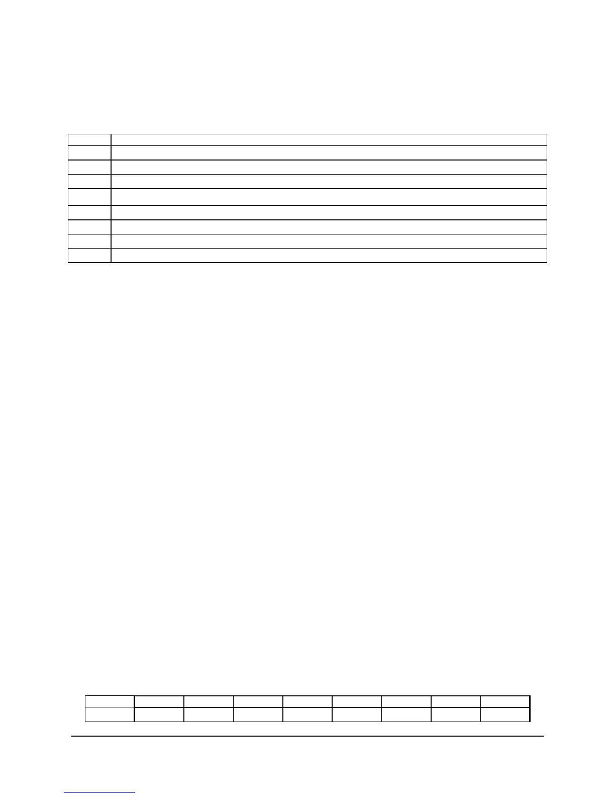
Table 74: POST Progress Code LED Example
LEDs Red Green Red Green Red Green Red Green
Ach 1 1 0 1 1 0 0 0
 Loading...


