Connectors and Jumper Blocks Intel® Server Board SE7520JR2
Revision 1.0
C78844-002
200
24 BB_FAN_LED6_R IN
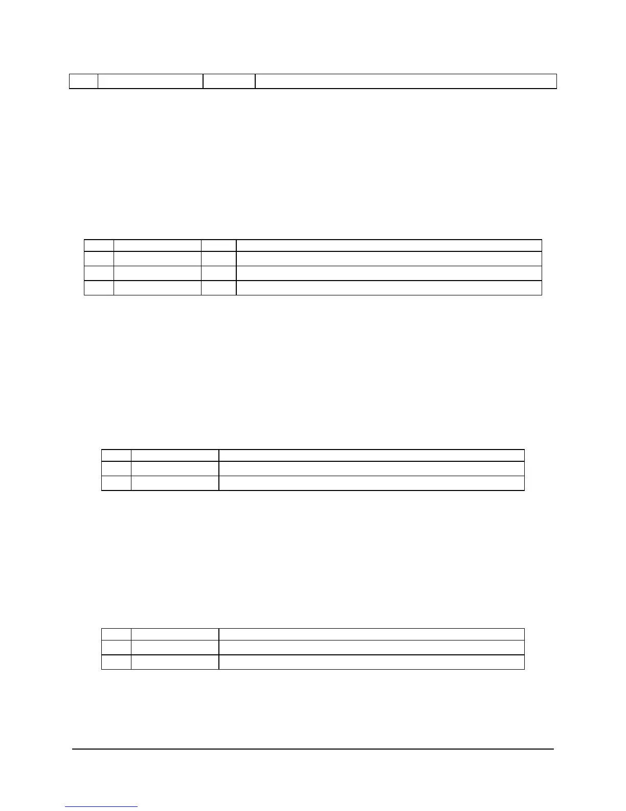
The 1x3 fan header (J3K3) is used to control a system fan in the Intel Server Chassis SR1400.
The pinout for this connector is found in the following table.
Table 108: 3-Pin Fan Speed Controlled Fan Header (J3K3)
Pin Signal Name Type Description
1 Fan Tach Out FAN_TACH signal is connected to the BMC to monitor the FAN speed
2 Fan_Speed_Cntl1 Power Power supplied through fan speed control circuitry
3 Ground GND GROUND is the power supply ground
7.7 Misc. Headers and Connectors
7.7.1 Chassis Intrusion Header
A 1x2 pin header (J1A1) is used in chassis that support a chassis intrusion switch. This header
is monitored by the mBMC. The pinout definition for this header is found in the following table.
Table 109: Chassis Intrusion Header (J1A1)
Pin Signal Name Description
1 FP_Chassis_Intr
2 Ground
7.7.2 Hard Drive Activity LED Header
A 1x2 pin header (J1A2) provides hard drive controller add-in cards an interface to the control
panel Hard Drive Activity LED. The pinout definition for this header is found in the following
table.
Table 110: Hard Drive Activity LED Header(J1A2)
Pin Signal Name Description
1 +3.3V
2 FP_LED_L
 Loading...


