Error Reporting and Handling Intel® Server Board SE7520JR2
Revision 1.0
C78844-002
174
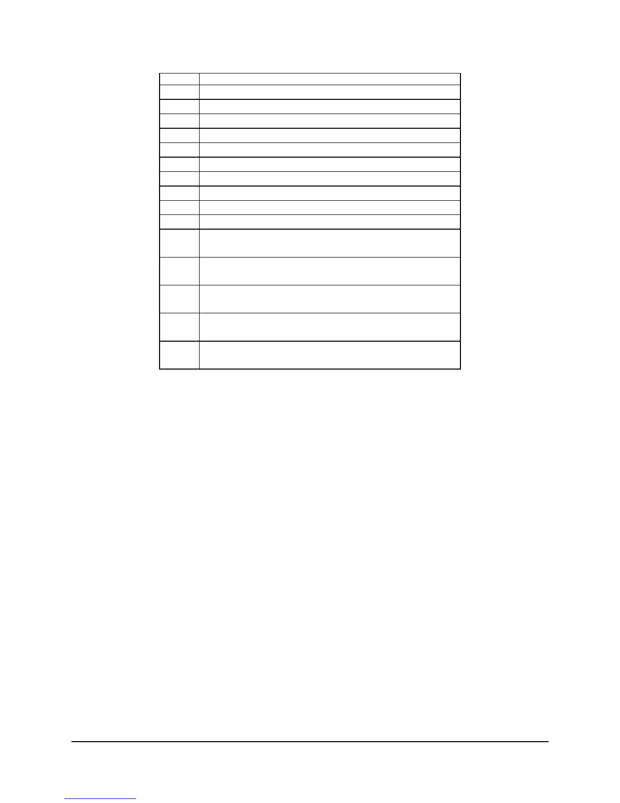
Tpoint Description
0E5h MEM_ERR_SIZE_MISMATCH
0E6h MEM_ERR_ECC_MISMATCH
0E8h MEM_ERR_ROW_ADDR_BITS
0E9h MEM_ERR_INTERNAL_BANKS
0EAh MEM_ERR_TIMING
0EBh MEM_ERR_INST_ORDER_ERR
0ECh MEM_ERR_NONREG_MIX
0EDh MEM_ERR_LATENCY
0EEh MEM_ERR_NOT_SUPPORTED
0EFh MEM_ERR_CONFIG_NOT_SUPPORTED
0F0h SYS_FREQ_ERR
(Flag for Unsupported System Bus Freq)
0F1h DIMM_ERR_CFG_MIX
(Usupported DIMM mix)
0F2h DQS_FAILURE
(indicates DQS failure)
0F3h MEM_ERR_MEM_TEST_FAILURE
(Error code for unsuccessful Memory Test)
0F4h MEM_ERR_ECC_INIT_FAILURE
(Error code for unsuccessful ECC and Memory Initialization)
6.6 Light Guided Diagnostics
The baseboard provides system fault/status LEDs in many areas of the board. There are fault
LEDs for each DIMM slot and for each processor, and status LEDs for 5-volt stand-by and
system state. Operation of some of these LEDs is dependant upon whether an IMM is installed
or not. With on-board platform instrumentation, there is limited diagnostic LED support.
• In systems configured with an IMM, the CPU 1 or CPU 2 led is lit to indicate the processor
is disabled. DC-Off or AC Cycle will cause the LED to turn off.
• CPU 1 and 2 LEDs are both lit to indicate the baseboard HW has discovered a
configuration error. If processor mis-population is detected when using standard on-board
platform instrumentation, baseboard hardware will illuminate both processor error LEDs. If
an IMM (Professional or Advanced editions) is used, the Sahalee BMC will generate a
series of beep codes when this condition is detected and will illuminate the processor 1
fault LED. An AC cycle will cause the LEDs to turn off.
• DIMM fault LEDs are lit by BIOS whenever BIOS disables a specific DIMM.
• The 5-Volt stand-by LED is always lit when 5-volt stand-by is present.
• The Status LED displays the state of the system. It mirrors the state of the Control Panel
Status LED. Valid states include: Solid Green, Blinking Green, Blinking Amber, Solid
Amber, and Off.
 Loading...


