4 / 36 P/N 146550999-1 • REV C • ISS 30APR12
• Strong air draughts onto the detector
• Animals in the field of view (DD1012(-D) detectors)
• Obscuring the detector field of view with large objects,
such as furniture
Microwave hazards:
• Mounting surface susceptible to vibrations
• Metal surfaces reflecting microwave energy
• Water movement through plastic pipes
• Moving or vibrating objects like fans, heating or air-
conditioning ducts
We recommend that the detector is regularly walk tested and
checked at the control panel.
To install the detector:
1. Lift off the custom insert (see Figure 2, items 1 and 2).
2. Using a screwdriver, carefully prise open the detector (see
Figure 2, items 3 and 4).
Caution: Do not touch the pyroelectric sensor (Figure 6).
3. Take out the cover screw (Figure 4, item 2).
4. Fix the base to the wall between 1.8 and 3.0 m (5.9 and
9.8 ft.) from the floor.
See Figure 4.
- For flat mounting, use a minimum of two screws
(DIN 7998) in positions A.
- For corner mounting, use screws in position B or C.
- To install the pry-off tamper ST400, use mounting
positions A or B. ST400 mounting position is shown as
item 3 in Figure 4. Open the outlet in the back plate
(Figure 5, item 2).
5. Wire the detector (see Figures 4 and 12). Use back plate
cable inlets (Figure 5, item 1) and cable gutter (Figure 5,
item 3).
6. Select the desired jumper and DIP switch settings (see
“Setting the detector” below for more information.
7.
Remove the blinders and add the stickers, if required. See
“Configuring the coverage pattern” on page 5 for more
detai
ls.
8. For ceiling-mount applications, use the SB01 swivel-mount
bracket. SB01 mounting position is shown as item 1 in
Figure 4.
9. Close the cover, insert the cover screw, and place the
custom insert.
Connections
See Figure 12.
Table 1: Detector Connections
Terminal Label Explanation
1, 2 GND, +12V Power supply connection (9 to 15 V,
12 V nominal)
3, 4 ALARM Alarm relay output (33 Ω). Use jumper JA to
set the onboard EOL resistor in series with
the relay. See “Jumpers” below.
5, 6 TAMPER Tamper switch output (0 Ω). Use jumper JT
to set the onboard EOL resistor in series
with the switch. See “Jumpers” below.
Terminal Label Explanation
7 Walk test This input enables and disables the LED
(walk test On/Off). Walk test mode can only
be entered when detector is in Day mode
(pin 8). Active high or low is determined by
SW1-3 (see “SW1-3: Polarity” on page 5).
8 Day/Night This input switches the detector in day
(show memory on the LED indicator) or
night mode (activates the alarm memory and
clears previous stored alarms). Active high
or low polarity is determined by SW1-3 (see
“SW1-3: Polarity” on page 5).
Notes
• Inputs 7 and 8 are only useable when SW1-5 is set to
Remote on. See “SW1-5: Remote functionality” on page 5.
•
The LED is only enabled when SW1-6 is set to LED on.
Figure 10 explains how to create a single zone with multiple
resistor configuration.
Figure 10 legend
(1) Alarm relay
(2) Alarm zone
(3) Tamper switch output
Ra Alarm EOL resistor
Rt Tamper EOL resistor
Setting the detector
See Figure 13 for jumpers and DIP switch location.
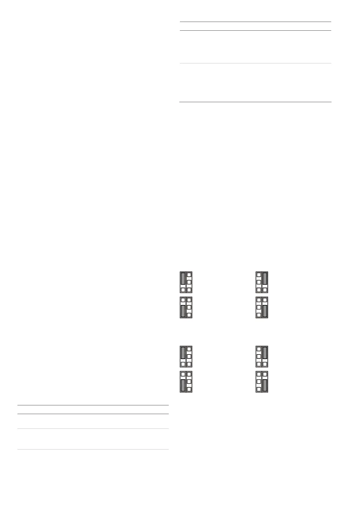
Jumpers
Jumpers set onboard EOL mode and value. The circuit is
shown in Figure 10.
JA: Set onboard alarm EOL resistor (Ra)
1 kΩ
2.2 kΩ
4.7 kΩ (factory
default)
5.6 kΩ
Off: No onboard alarm EOL.
JT: Set onboard tamper EOL resistor (Rt)
1 kΩ
2.2 kΩ
4.7 kΩ (factory
default)
5.6 kΩ
Off: No onboard tamper EOL.
Configuring the zone
To set up the zone, apply the following guidelines.
• Select appropriate EOL resistor values with JA and JT.
For example, setting of jumper JT determines Rt value.
• For isolated outputs remove JT.
• Remove jumpers JA and JT to exclude onboard EOL
values.
 Loading...